


22 Assembly
MAN0884 (08/15/2011)
ASSEMBLY INSTRUCTIONS
DEALER SET-UP INSTRUCTIONS
Assembly of this snowblower is the responsibility of the
Woods dealer. It should be delivered to the owner com-
pletely assembled, lubricated and adjusted for normal
conditions.
The snowblower is shipped partially assembled.
Assembly will be easier if components are aligned and
loosely assembled before tightening hardware. Rec-
ommended torque values for hardware are located on
page 33.
Select a suitable working area. A smooth hard surface,
such as concrete, will make assembly much quicker.
Open parts boxes and lay out parts and hardware to
make location easy. Refer to illustrations, accompany-
ing text, parts lists and exploded view drawings.
All Models
1. Remove parts from skid in a suitable work area.
Check packing list to ensure all parts are present.
NOTE: Leave all hardware loose until all compo-
nents are completely assembled.
2. Remove driveshaft from snowblower. Slide imple-
ment PTO shaft on gearbox shaft. Pull back spring
actuated collar as driveline is installed on gearbox
shaft, releasing collar when driveline is installed.
NOTE: Check that drive shaft is fully engaged in
gearbox shaft groove.
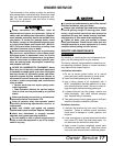
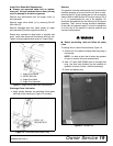
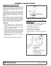
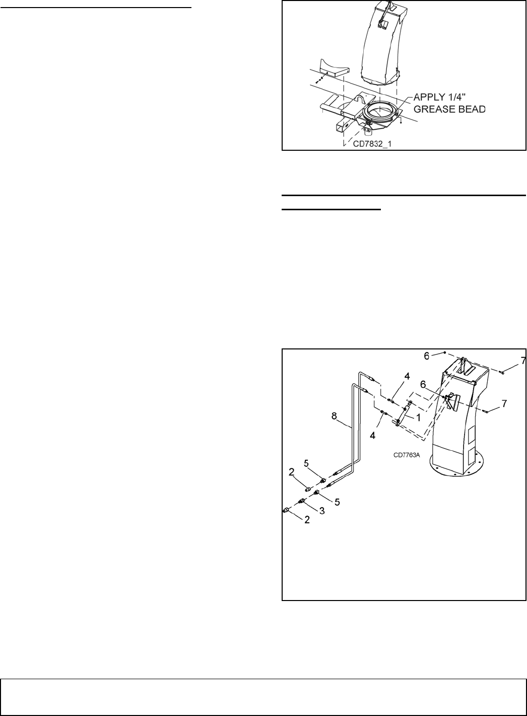
3. Apply grease to discharge tube ring and frame.
Figure 16. Apply Grease to Discharge Chute Ring
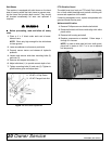
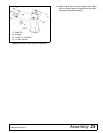
MOUINTING HYDRAULIC CHUTE DEFLEC-
TOR (FIGURE 17)
1. Fasten cylinder (1) to discharge chute (8) using
hardware (6) and (7). Do not over tighten.
2. Fasten elbows (4) to cylinder (1).
3. Fasten hoses (8) to elbows (4).
4. Fasten adapters (5) to hoses (8).
5. Fasten restrictor (3) to adapter (5).
6. Fasten couplers (2) to adapter (5) and restrictor
(3).
1. Hydraulic Cylinder
2. Male Coupler
3. Swivel Restrictor
4. Elbow
5. 1/2 NPTF x 1/2 NPTM Adapter
6. 3/8 NC Lock Nut
7. 3/8 NC x 1-3/4 HHCS
8. 1/4 Hydraulic Hose