


Operation 11
MAN0884 (08/15/2011)
The snowblower is mounted on a tractor 3-point hitch
and driven by the tractor PTO. A centrally located gear-
box directs power to the fan and auger.
TRACTOR REQUIREMENTS
3-Point Hitch
The SS snowblower requires the tractor to be equipped
with a Category 2 or 3, three-point hitch.
Hydraulic Circuit
Either closed-center or open-center systems can be
used for the hydraulic chute rotator and optional spout
control.
Tire Configuration
For best results, the tractor wheels should be set nar-
rower than the cutting width of the snowblower. Wider
wheel settings will cause snow to be pulled under the
tractor and may require additional passes.
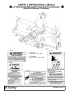
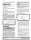
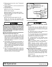
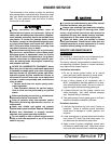
Tractor Stability
A minimum 20% of tractor and equipment
weight must be on the tractor front wheels when
attachments are in transport position. Without this
weight, front tractor wheels could raise up result-
ing in loss of steering. The weight may be attained
with front wheel weights, ballast in tires or front
tractor weights. Weigh the tractor and equipment.
Do not estimate.
Figure 1. Tractor Stability (Typical)
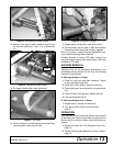
HITCH ADJUSTMENT
Before putting equipment into service, check
and adjust driveline length as instructed in Opera-
tor's Manual. Driveline must not bottom out or pull
apart throughout the full range of the tractor hitch.
Do not operate until driveline length is correct.
Never go underneath equipment (lowered to the
ground or raised) unless it is properly blocked and
secured. Never place any part of the body under-
neath equipment or between moveable parts even
when the engine has been turned off. Hydraulic
system leak down, hydraulic system failures,
mechanical failures, or movement of control levers
can cause equipment to drop or rotate unexpect-
edly and cause severe injury or death. Follow Oper-
ator's Manual instructions for working underneath
and blocking requirements or have work done by a
qualified dealer.
Keep all persons away from operator control
area while performing adjustments, service, or
maintenance.
The snowblower has an adjustable hitch for estab-
lishing the proper PTO operating geometry. You
must perform the following procedure for each
tractor or quick hitch used.
Follow the above safety rules and securely block the
snowblower with jackstands when taking measure-
ments. Always stand alongside of hitch and never go
underneath any raised components. The tractor must
be shut off, parking brake set, and key removed each
time the operator leaves the tractor seat during this
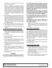
procedure. Refer to Figure 2.
1. Clear the area of all bystanders.
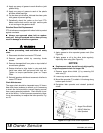
Figure 2. 3-Point Hitch Adjustment Positions
2. The snowblower 3-point hitch arms are adjustable
to three operating positions. Assemble the arms in
their shortest position (A) and adjust for proper
PTO driveline engagement before using. Remove
adjustment bolts from snowblower lower arms and
top link arm. Slide the arm assembly to the correct
mounting hole and install adjustment bolts. Torque
bolts to specifications in Bolt Torque Chart on page
32.
3. Attach snowblower to tractor, but do not attach
PTO shaft.
4. Move snowblower until tractor PTO and gearbox
shafts are the same height. This should be the
position requiring the shortest driveline length.
Securely block both ends of snowblower housing
using jackstands.
5. Measure the distance between the lock groove on
tractor PTO shaft and the cross hole in snowblower
gearbox shaft. The distance between the groove
and cross hole must be greater than 37.5" to
provide one inch of compression space in the shaft
and prevent bottoming out during use.
6. If the dimension is less than 37.5", the hitch must
be extended to mounting hole B. Recheck the
AWARNING