


24 Assembly
MAN0869 (04/13/2011)
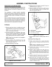
MOUINTING HYDRAULIC CHUTE DEFLEC-
TOR (FIGURE 25)
1. Fasten cylinder (1) to discharge chute (8) using
hardware (6) and (7). Do not over tighten.
2. Fasten elbows (4) to cylinder (1).
3. Fasten hoses (8) to elbows (4).
4. Fasten adapters (5) to hoses (8).
5. Fasten restrictor (3) to adapter (5).
6. Fasten couplers (2) to adapter (5) and restrictor
(3).
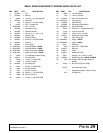
Figure 23. Hydraulic Chute Deflector Installation
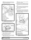
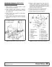
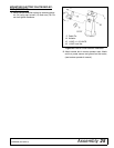
MOUNTING ELECTRIC CHUTE ROTATOR
OPTION (FIGURE 25)
1. Remove rotator sprocket from lower hitch pin.
Position rotator sprocket in square opening on
chute adapter with hole facing towards hitch. Install
shaft (7) into rotator sprocket (36) using roll pin (6).
Make sure second hole on shaft is facing towards
hitch.
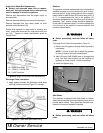
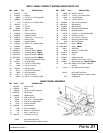
2. Fasten rotary actuator (1) to mounting bracket (3)
using hardware from actuator.
3. Fasten mounting bracket (3) and actuator (1) to
upper three point channel using cap screws (12),
link (8), and nuts (13). Leave hardware loose (See
Figure 24).
Figure 24. Motor Mount Position 6.62" from Front
4. Fasten coupler (4) to shaft (7) with roll pin (6).
5. Slide rotary actuator and channel assembly into
coupler (4) and attach with roll pin (6). Tighten
loose hardware.
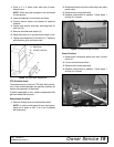
Install Wiring Harness
6. Attach connector "A" to the rotary actuator (1), (12"
long from splice).
NOTE: Attach connector "B" to linear actuator on
deflector, if equipped, (36" long from splice).
7. Tie the wire harness away from movable parts and
pinching points using cable ties (5).
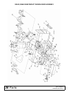
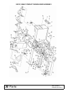
Figure 25. Electric Chute Rotator Installation
1. Hydraulic Cylinder
2. Male Coupler
3. Swivel Restrictor
4. Elbow
5. 1/2 NPTF x 1/2 NPTM Adapter
6. 3/8 NC Lock Nut
7. 3/8 NC x 1-3/4 HHCS
8. 1/4 Hydraulic Hose
12. 3/8 NC x 4 HHCS
13. 3/8 NC Locknut
1. Hydraulic Motor
2. Wire Harness
3. Mounting Bracket
4. Coupler
5. Cable Tie
6. Roll Pin
7. Shaft Rotator
8. Mounting Link
9. Spring Nut
10. Thumb Screw
11. Rotator Shield
12. 3/8 NC x 4 HHCS
13. 3/8 NC Lock Nut
36. Rotator Sprocket