


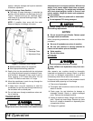


Assembly
21
MAN0869 (04/13/2011)
ASSEMBLY INSTRUCTIONS
DEALER SET-UP INSTRUCTIONS
Assembly of this snowblower is the responsibility of the
Woods dealer. It should be delivered to the owner com-
pletely assembled, lubricated and adjusted for normal
conditions.
The snowblower is shipped partially assembled.
Assembly will be easier if components are aligned and
loosely assembled before tightening hardware. Rec-
ommended torque values for hardware are located on
page 38.
Select a suitable working area. A smooth hard surface,
such as concrete, will make assembly much quicker.
Open parts boxes and lay out parts and hardware to
make location easy. Refer to illustrations, accompany-
ing text, parts lists and exploded view drawings.
All Models
1. Remove parts from crate in a suitable work area.
Check packing list to ensure all parts are present.
NOTE: Leave all hardware loose until all compo-
nents are completely assembled.
2. Remove driveshaft from snowblower. Slide imple-
ment PTO shaft on gearbox shaft. Pull back spring
actuated collar as driveline is installed on gearbox
shaft, releasing collar when driveline is installed.
NOTE: Check that drive shaft is fully engaged in
gearbox shaft groove.
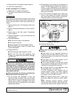
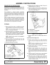
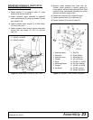
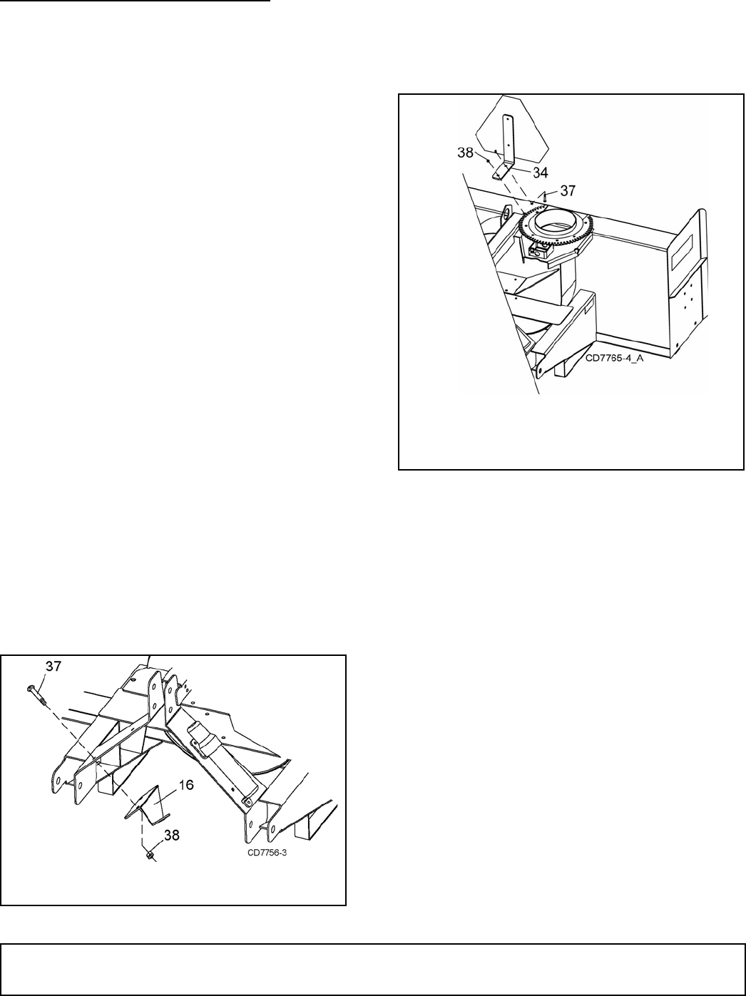
3. Remove hardware (37) and (38) from front right
mast plate hole and rotate drive holder (16) until
holes are aligned, Figure 16.
4. Reinstall hardware (37) and (38).
Figure 16. Install Drive Holder
5. Remove plug from gearbox and add .52 quart of
SAE85W-90 gear oil, Figure 12.
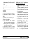
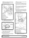
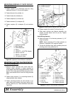
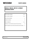
6. Remove hardware (37) and (38) from SMV bracket
(34) and rotate bracket facing up. Reinstall hard-
ware (37) and (38), Figure 17.
Figure 17. SMV Installation
7. Remove plastic cable tie holding auger chain in
place.
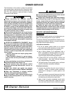
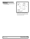
Install Hand Crank (Figure 18)
8. Fasten mount bracket (5) to upper three-point
channel using two carriage bolts (8) and lock nuts
(9).
NOTE: Bracket is adjustable and can be rotated or
slide up or down for best fit with tractor.
9. Connect clevis rotator (1) to block (2) and clevis
tube (3) with roll pins (6).
10. Remove rotator sprocket from lower hitch pin.
Install in square opening on chute adapter with
block and pin assembly using roll pins (6) and (13).
Hole in sprocket rotator should face towards tractor
hitch.
11. Install trim strip (6.5" long) in slot on mount bracket
(5) which hand crank (4) will protrude through.
12. Slide hand crank (4) through mount bracket (5)
and into clevis tube (3). Align hand crank and cle-
vis tube holes for correct length and install cap
screws (7) and hex nut (9).
16. Drive Holder
37. 5/16 NC x 1" Carriage Bolt
38. 5/16 NC Lock Nut
34. SMV Bracket
37. 5/16 NC x 1" Carriage Bolt
38. 5/16 NC Hex Locknut
(Rev. 10/4/2011)