


22 Assembly
MAN0869 (04/13/2011)
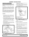
NOTE: Make sure handle will not protrude into rear
window of a tractor equipped with cab by checking
the highest 3-point hitch position.
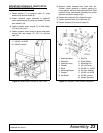
Figure 18. Hand Crank Installation
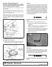
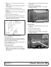
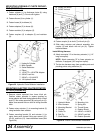
13. Apply grease to discharge tube ring and frame.
Figure 19. Apply Grease to Discharge Chute Ring
14. Loosen discharge chute hardware and remove
washers. Washers will not be reused.
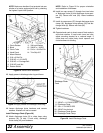
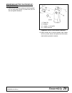
Install Discharge Chute (Figure 20)
15. Attach discharge chute (8) to chute base using
spacers (35), (6 total, 3 each side), discharge
chute clamp (40), and hardware.
NOTE: Refer to Figure 20 for proper orientation
and installation of hardware.
16. Install two cap screws (5) through front two holes
of discharge chute (8) and discharge chute spac-
ers (35). Secure with nuts (28). Leave hardware
loose.
17. Install six cap screws (27) through discharge chute
clamp (40), discharge chute spacers (35) and dis-
charge chute (8). Secure with nuts (28).
18. Tighten hardware.
19. Operate hand crank to check ease of block and pin
and chute rotation. If hand crank turns too hard,
adjust mounting bracket for a reduced angle. If
chute does not rotate freely check spacers and
chute hardware for binding.
Figure 20. Install Discharge Chute
1. Clevis Rotator
2. Block
3. Clevis Tube
4. Hand Crank
5. Mount Bracket
6. 5/16 x 2 Roll Pin
7. 5/16 NC x 1-1/2 HHCS
8. 5/16 NC x 1 Carriage Bolt
9. 5/16 NC Lock Nut
10. Rotator Shield
11. 3/8 Lock Washer
12. 3/8 NC x 1 HHCS
13. 5/16 x 1-3/4 Roll Pin
14. Trim Strip 6.5"
5. 3/8 NC x 1-1/2 HHCS GR5
8. Discharge Chute
27. 3/8 x 1-1/4 HHCS GR5
28. 3/8 NC Hex Locknut
35. Discharge Chute Spacer
40. Discharge Chute Clamp
(Rev. 10/4/2011)