


24 Assembly
15148 (Rev. 2/9/2007)
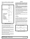
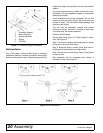
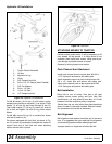
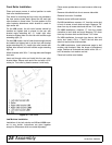
Hydraulic Lift Installation
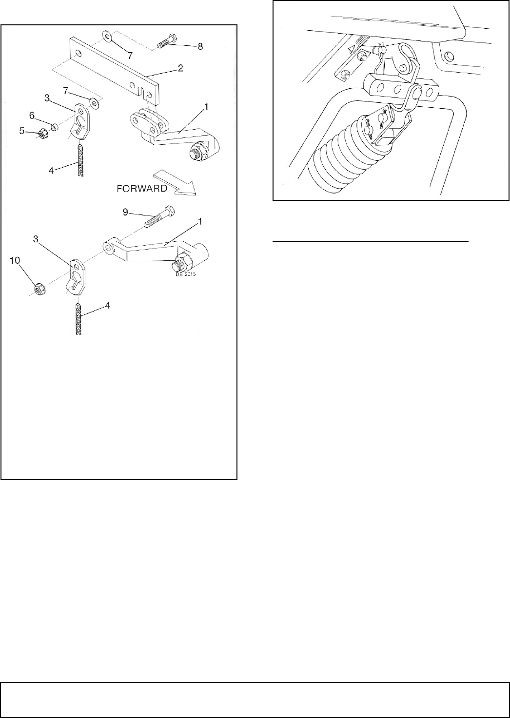
Figure 18. Hydraulic Lift Installation
For IH A tractors, pin lift arm (2) with tractor spring-
loaded locking device to rockshaft (1) as shown. Place
washer (7) on bolt (8) and insert through lift bar (2).
Then install washer (7), lift lug (3), sleeve (6), and nut
(5) on bolt and tighten. Be sure lift lug pivots around
sleeve.
For IH 140, secure lift lug (3) to rockshaft as shown
with bolt (9) and nut (10).
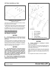
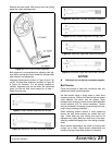
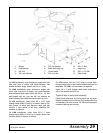
On tractors equipped with fast hitch, as shown in Fig-
ure 19, be sure to use bracket furnished with tractor to
support front end of fast hitch ball when attaching
mower with fast hitch in place.
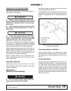
Figure 19. Fast Hitch
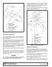
ATTACHING MOWER TO TRACTOR
Position mower under tractor. It will be necessary to lift
front wheels off the ground. If a lifting device is not
available, back tractor over mower, using care to pre-
vent damage to painted surface of mower.
Remove by driving forward over mower.
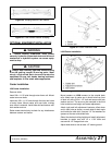
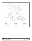
Push Channel Arm Attachment
Install push channel arms to mower deck with 5/8 x
1-1/2" clevis pins and secure with safety pins.
Attach crosswise support to push channel arms with
5/8 x 1/2" clevis pins and secure with safety pins.
Attach push channel arms to idler bracket with 5/8 x
1-3/4" clevis pins and secure with safety pins.
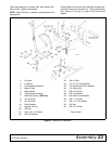
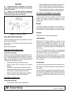
Belt Installation
Bring belt to rear of tractor. Give belt a 3/4 twist
between mower center pulley and front idler. Belt
should have a 1/4 twist ahead of rear idler. A 1/2 twist
between front idler and drive pulley is required.
Should there be any twist other than those described
above, the belt is incorrectly installed. Recheck installa-
tion procedures and correct as necessary.
Belt Alignment
Belt alignment and tension should be set at the same
time. It is suggested that you read both the alignment
and tensioning sections before attempting either.
Improper tension or alignment will affect belt life.
1. Tractor Center Rockshaft
2. Lift Arm
3. Keyhole Lift Lug
4. Chain
5. 3/8" Flanged Lock Nut
6. 3/8 x 1/2 x 1/2" Sleeve (Heat-Treated)
7. 3/8" Flat Washer
8. 3/8 x 1-1/2" Bolt
9. 1/2 x 2-1/2" Bolt
10. 1/2" Flange Lock Nut