


16 Dealer Service
15148 (Rev. 2/9/2007)
Proper seal installation is important. An improperly
installed seal will leak and could cause bearing failure.
Lightly coat area of housing where seals seat with Per-
matex
®
.
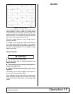
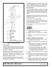
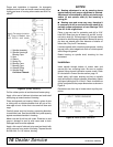
Figure 8. Spindle Assembly
Pull the rubber portion of seal back and locate spring.
Apply a thin coat of lubricant to bottom seal and install
with spring up toward center of housing.
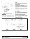
Place seal squarely on housing. Select a piece of pipe
or tubing with an outside diameter that will set on out-
side edge of seal. A tube that is too small will bow seal
cage.
Carefully press seal into housing, preventing distortion
to metal seal care. Seal should seat firmly and squarely
against machined shoulder in housing.
Make sure seal lip did not roll under. Distortion to seal
cage or damage to seal lip with cause seal to leak.
Damaged seals must be replaced.
Apply a thin coat of lubricant to top seal and install with
spring up away from center of housing. Top seal should
be flush with, to 1/16" above, housing.
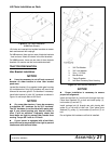
NOTICE
■ Bearing adjustment is set by pressing sleeve
against bearing until proper adjustment is attained.
Adjustment is maintained by drilling a hole through
sleeve (4) and spindle shaft (9) and inserting a
spring pin.
■ Bearing cups and cones may vary; therefore it
is necessary to drill a new hole through shaft (9) to
maintain proper adjustment of new bearings. Drill
hole 90° to the original hole.
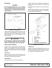
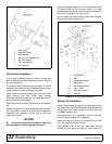
Place a rag over seal for protection and drill a 3/16"
hole 9/32" down from top of sleeve (4) and 90° to origi-
nal hole in shaft (9). Drive spring pin (5) through sleeve
and shaft to hold bearing adjustment. Make sure spring
pin does not extend past outer diameter of sleeve on
either side. File pin off if necessary.
Lubricate spindle with a medium grade grease, venting
top seal with a blunt edged tool such as a letter opener
while filling with grease.
Rotate housing on spindle shaft, checking for free
movement.
Installation
Insert spindle through bottom of mower deck and
secure with four mounting bolts. Be sure to position
grease fittings toward lubrication access areas. Refer
to Lubrication in Owner Service section, page 12.
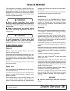
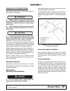
Install pulley, split taper bushing and key on spindle
shaft and adjust to height indicated. Alternately tighten
split taper bushing bolt to 12 lbs-ft. Check to make sure
pulley is adjusted to the proper dimensions as shown in
Figure 9.
Dimensions are from top of mower deck to pulley cen-
terline.
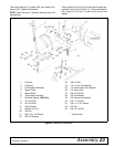
Figure 9. Blade Spindle Installation
1. Spindle Assembly
2. Spindle Housing &
Bearing Cups
3. Seal
4. Sleeve
5. Spring Pin
6. Bearing Cone
7. Bearing Cups
8. Grease Fitting
9. Spindle Shaft,
Left Hand Threads