


Assembly 41
MAN0137 (9/14/01)
Assembly Instructions
Cont’d
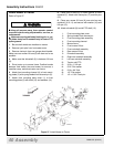
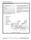
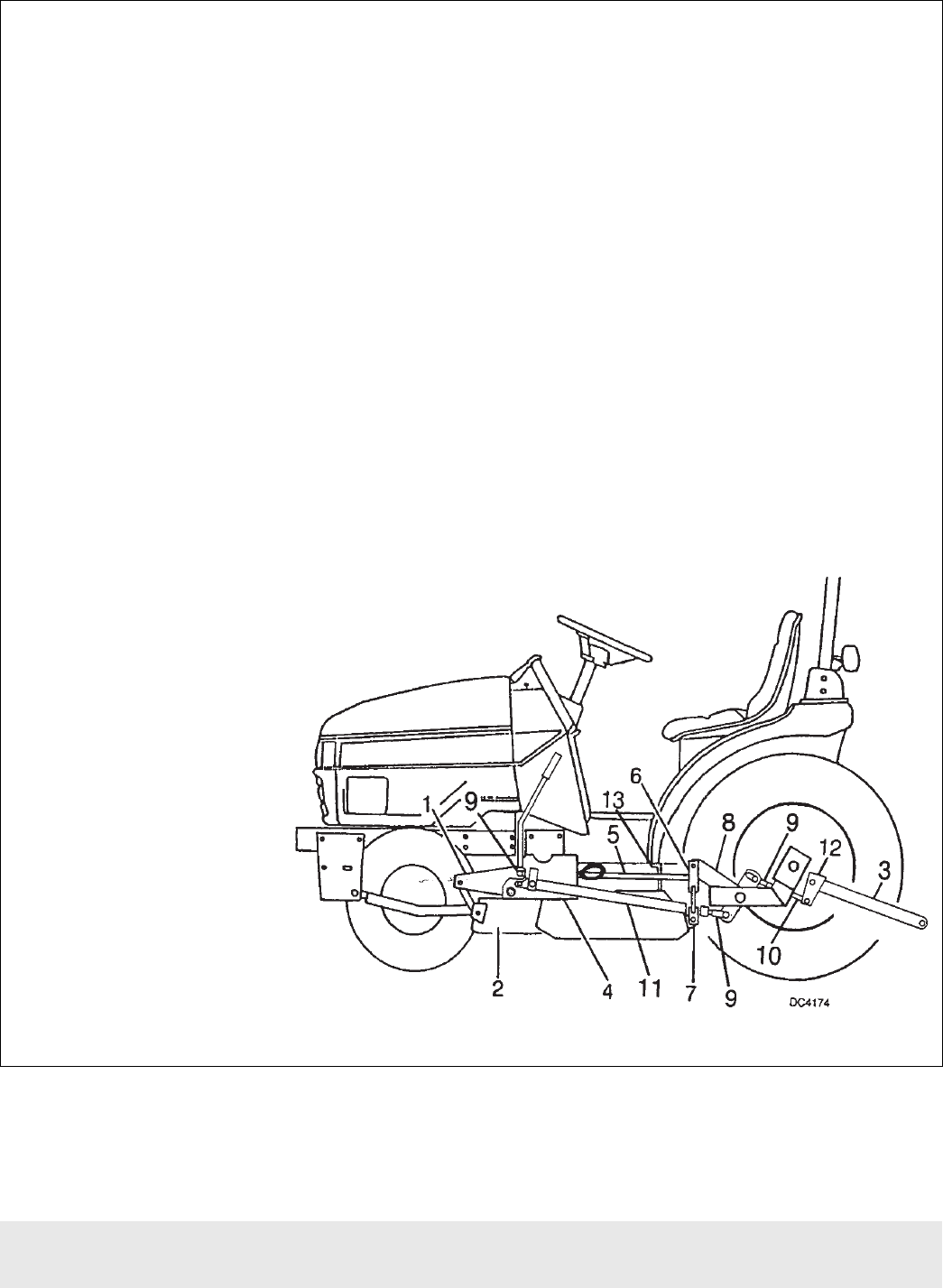
Adjust Mower with Mechanical Lift
1. Remove clevis pin connecting rear pull rod (10) to
the rear lift arm assembly (12).
2. Raise tractor lower 3-point lift arms (3) to their
highest position.
3. Remove clevis pin that connects clevis yoke (9) to
front rockshaft (1).
4. Block mower frame (2) up against front lift stop
(4) and so rear lift stop (13) contacts tractor transmis-
sion.
5. With tractor lower 3-point arms (3) in their highest
position, rotate rear rockshaft (8) up and adjust rear
pull rod (10) until clevis pin connecting rear pull rod
(10) to rear lift arm assembly (12) just slips in. Install
clevis pin and secure with cotter pin.
6. Rotate front rockshaft assembly (1) up and adjust
clevis yoke (9) on pull rod (5) until clevis pin just slips
in. Install clevis pin and secure with cotter pin.
7. Remove block from mower frame. The deck will
drop slightly. Readjust clevis (9) and rear pull rod (10)
so mower just contacts lift stops when 3-point arms
are at maximum lift height.
8. With tractor 3-point arms at their maximum lift
height, adjust lock-up bar (11) and clevis (9) so slot on
lock-up bar will just drop into lock position. Spread
cotter pin on clevis pin that connects clevis yoke (9) to
rear rockshaft (8).
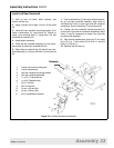
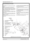
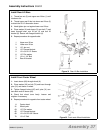
Figure 38 Mechanical Lift Adjustment
1. Front rockshaft assembly
2. Mower frame
3. 3-Point lift arm
4. Front lift stop
5. Pull rod
6. Upper rear lift link
7. Lower rear lift link
8. Rear rockshaft assembly
9. Adjustable clevis yoke
10. Rear pull rod
11. Lock-up bar
12. Rear lift arm assembly
13. Rear lift stop