


40 Assembly
MAN0137 (9/14/01)
Assembly Instructions
Cont’d
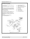
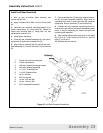
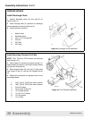
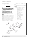
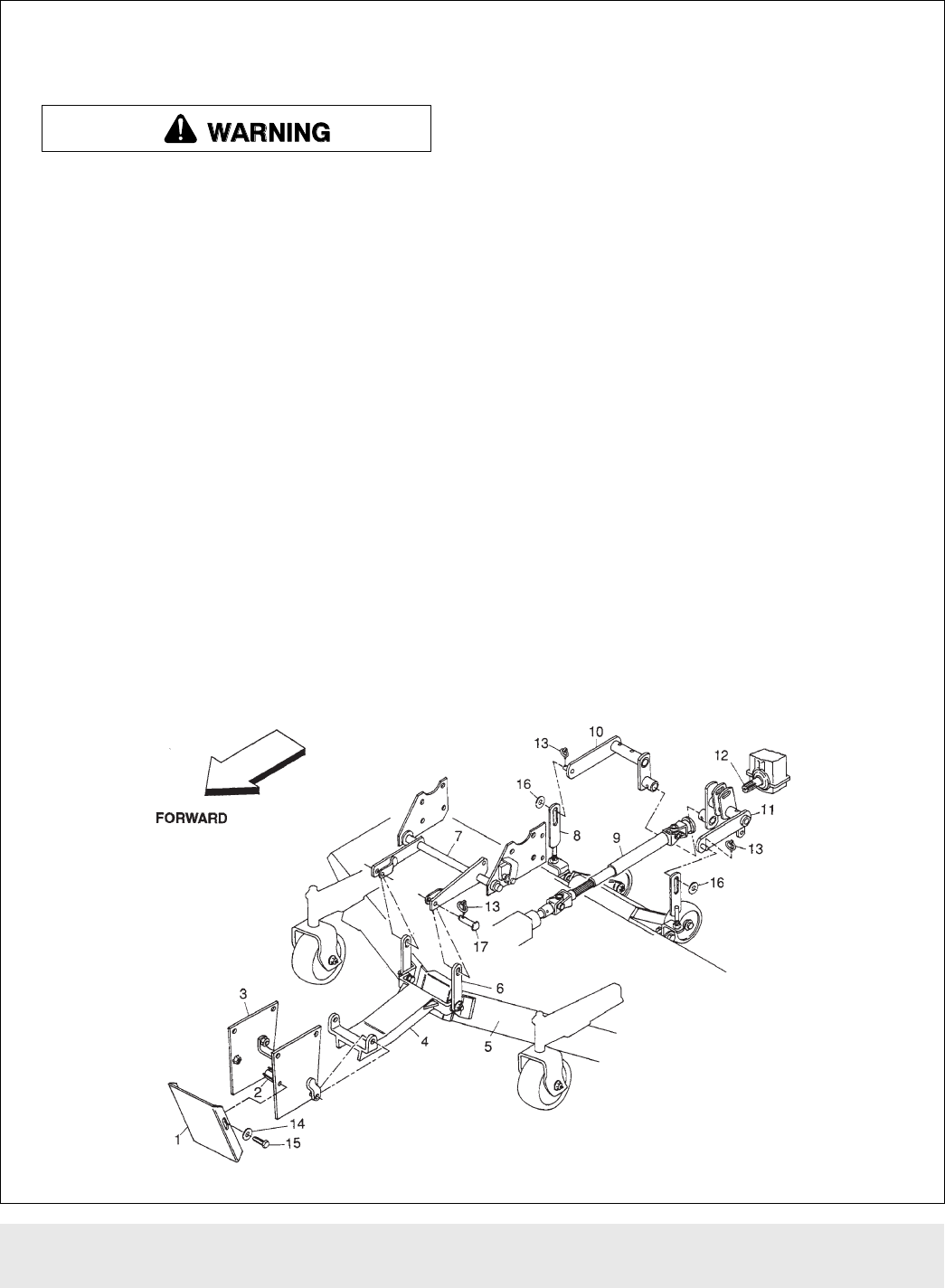
Attach Mower to Tractor
Refer to Figure 37.
Keep all persons away from operator control
area while performing adjustments, service, or
maintenance.
Make sure spring-activated locking pin or col-
lar slides freely and is seated firmly in tractor PTO
spline groove.
1. Be sure belt shields are installed on mower.
2. Remove lynch pins from front caster arms.
3. Remove clevis pin from rear gauge wheel handle.
Make sure rear mower lift bars (8) are down as far as
possible.
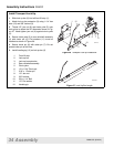
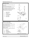
4. Make sure that driveshaft (9) is between lift bars
(8).
5. Drive tractor up to mower frame. Position boards
between front tractor tires and mower to serve as a
transition ramp, and drive tractor over frame.
6. Attach front mounting channel (4) to front mount-
ing plates (3) with spring-loaded front channel pin (2).
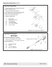
7. Attach front mounting plate cover (1) to front
mounting plates (3) with bolts (15) and washers (14).
8. Place front lift bars (6) in clevis portion of front
rockshaft (7). Attach with clevis pins (17) and klik pins
(13).
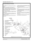
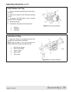
9. Place rear mower lift bars (8) over stud on rear
rockshaft (10 & 11) and secure with washer (16) and
Klik pin (13).
10. Attach driveshaft (9) to mid-PTO shaft (12).
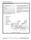
1. Front mounting plate cover
2. Spring-loaded front channel pin
3. Front mounting plate assembly
4. Front mounting channel
5. Mower frame
6 Front mower lift bar
7. Front rockshaft assembly
8. Rear mower lift bar
9. Driveshaft assembly
10. Right rear rockshaft assembly
11. Left rear rockshaft assembly
12. Tractor mid-PTO
13. 3/16 x 1" Klik pin
14. 5/16" Flat washer
15. 5/16 x 3/4" Bolt
16. 1/2" Flat washer
17. 1/2 x 1-3/4" Clevis pin
Figure 37 Attach Mower to Tractor
DB4200A