30 Assembly
MAN0137 (9/14/01)
Assembly Instructions
Cont’d
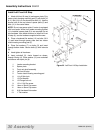
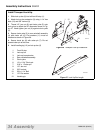
Install Left Front Lift Stop
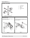
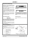
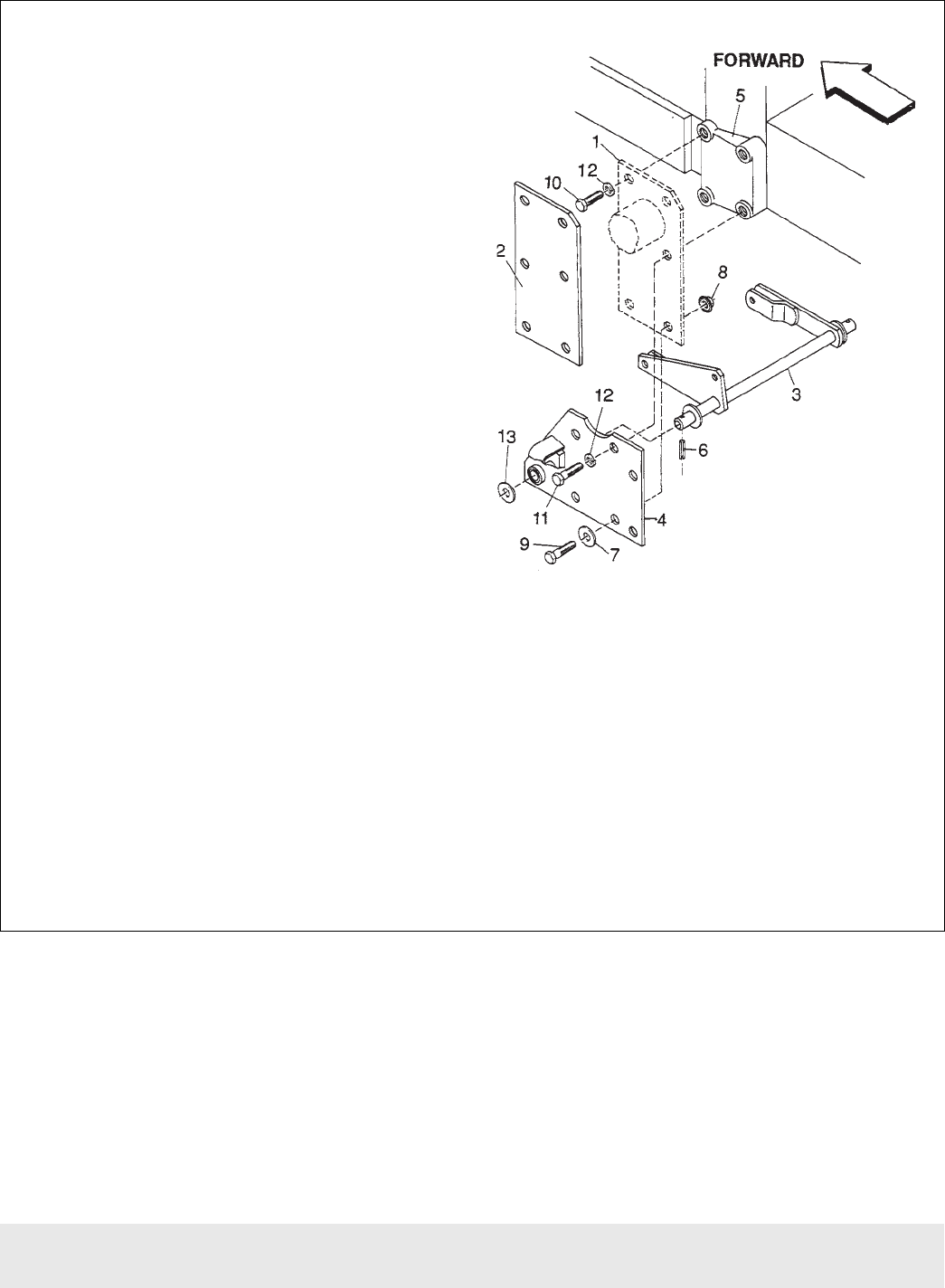
1. Attach left front lift stop (4) and spacer plate (2) to
tractor clutch housing mounting pad (5) with bolts (10
& 11). Bolt (10) is 5 mm shorter than bolt (11). Use the
shorter bolts in the top holes of spacer plate (2) and
bolts (11) in the center holes.
NOTE: Do not use spacer plate if tractor is equipped
with front loader. When front loader mounting bracket
(1) is installed, spacer plate (2) is not required. Do not
use hardware from loader bracket to install left front
lift stop (4); use the hardware supplied with mower.
2. Place a hardened flat washer (12) on bolts (10 &
11) and insert through spacer plate and into tractor
clutch housing mounting pad (5).
3. Place flat washers (7) on bolts (9) and insert
through bottom holes. Secure bolts (9) with locknuts
(8).
4. Hand tighten all hardware.
5. Insert rockshaft (3), clevis forward as shown,
through lift stop (4). Place washer (13) over rockshaft
and secure with spirol pin (6).
1. Loader mounting bracket
2. Spacer plate
3. Front rock shaft assembly
4. Left front lift stop
5. Tractor clutch housing mounting pad
6. 1/4 x 2 Spirol pin
7. 1/2 Flat washer
8. 1/2 Flange lock nut
9. 1/2 x 1-3/4 Cap screw
10. 14mm x 35mm Cap screw
11. 14mm x 40mm Cap screw
12. 9/16 Hardened flat washer
13. 1” Flat washer
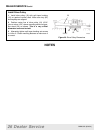
Figure 22 Left Front Lift Stop Installation


