


Assembly 35
MAN0137 (9/14/01)
Assembly Instructions
Cont’d
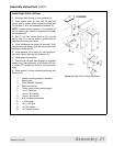
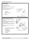
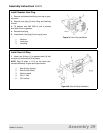
Assemble Mechanical Lift Pull Rod
1. Thread jam nut (17) onto pull rod (7) until it bot-
toms out.
NOTE: For tractor models 7000, 7200, and 7205, use
pull rod (7A) with bend up to clear hydraulic line.
2. Thread clevis yoke (8) onto pull rod (7) to obtain a
33-1/4" dimension from center to center between the
clevis and rod holes as shown. Hand tighten jam nut
(17) against clevis yoke (8).
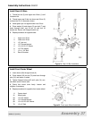
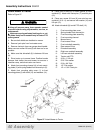
3. Attach pull rod assembly (17) to lug (21) on left
rear rockshaft (6) and secure with washer (15) and
cotter pin (16).
4. Connect clevis yoke (8) to front rockshaft (1) with
clevis pin (12) and secure with cotter pin (16). Do not
spread pin at this time.
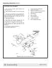
5. Remove left lower 3-point arm (9) from lift mount-
ing plate (4).
6. Remove the three axle housing bolts (19) and
replace lift mounting plate (4) with the lift mounting
plate supplied with mower lift kit.
7. Reinstall the three 12mm bolts and torque to 75
lbs.-ft.
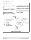
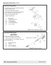
8. Slide rear lift arm assembly (5) over lower 3-point
arm (9) and slide both onto pin of lift mounting plate
(4). Secure with Klik pin (10).
9. Thread clevis yoke (8) onto rear pull rod (3) to
obtain 16.5" length.
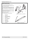
10. Connect rear pull rod (3) to rear rockshaft (6)
using clevis pin (14) and secure with washer (13) and
cotter pin (16).
11. Connect clevis yoke (8) to rear lift arm assembly
(5) with clevis pin (11) and cotter pin (16).
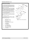
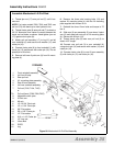
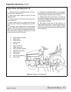
Figure 28 Mechanical Lift Pull Rod Assembly
DC4203B
1. Front rockshaft assembly
2. Left front lift stop
3. Rear pull rod
4. Lift mounting plate assembly
5. Rear lift arm assembly
6. Left rear rockshaft assembly
7. Pull rod (7192, 7194, 7195)
or
7A. Pull rod (bent) (7000,7200,7205)
8. Adjustable clevis yoke
9. 3-Point arm
10. Klik pin
11. 1/2 x 2-3/4" Clevis pin
12. 1/2 x 1-3/4" Clevis pin
13. 5/8" Flat washer
14. 5/8 x 1.65" Clevis pin
15. 1/2" Flat washer
16. 3/16 x 1-1/2" Cotter pin
17. 1/2" Jam nut
19. 12mm Bolt
20. ROPS
21. Lug