8
NOTE: You may now roll your riding
mower off the skid. Follow the ap pro pri ate
instruction below to remove the riding mower
from the skid.
CHECK TIRE PRESSURE
The tires on your riding mower were
overinflated at the factory for shipping pur-
poses. Correct tire pressure is important
for best cutting performance.
• Reduce tire pressure to PSI shown on
tires.
CHECK DECK LEVELNESS
For best cutting results, mower housing
should be properly leveled. See “TO LEVEL
MOWER HOUSING” in the Service and
Adjustments section of this manual.
CHECK FOR PROPER POSITON OF
MOWER DRIVE BELT
See the figure that is shown for replacing
the mower drive belt in the service and
adjustment section of this manual. Verify
that the belt is routed correctly.
CHECK BRAKE SYSTEM
After you learn how to operate your rid-
ing mower, check to see that the brake
is operating properly. See “TO ADJUST
BRAKE” in the Service and Adjustments
section of this manual.
02464
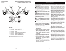
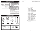
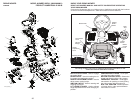
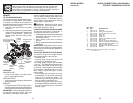
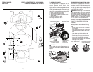
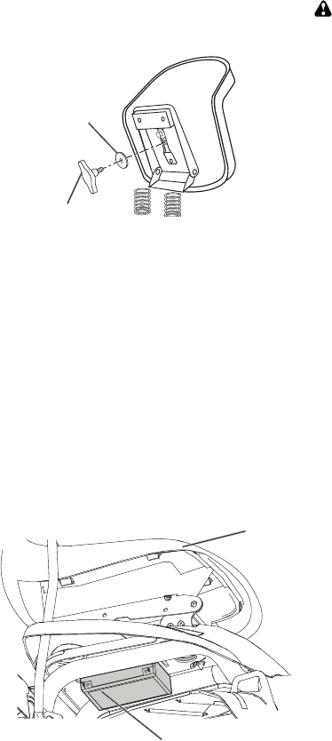
Adjustment Knob
Flat Washer
4. Pivot seat and pan forward and as sem ble
adjustment knob and flat washer loosely.
Do not tighten.
5. Lower seat into operating position and
sit in seat.
6. Slide seat until a comfortable position is
reached which allows you to press clutch/
brake pedal all the way down.
7. Get off seat without moving its ad just ed
position.
8. Raise seat and tighten adjustment knob
securely.
CHECK BATTERY
Make sure battery is securely fastened,
and that all wires are securely connected.
• Battery is located under the seat.
• Battery has been fully charged from the
factory, before installation.
Battery
Seat
WARNING: Before starting, read, un-
der stand and follow all in struc tions in the
Operation section of this manual. Be sure
riding mower is in a well-ventilated area.
Be sure the area in front of riding mower is
clear of other people and objects.
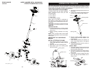
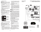
TO ROLL RIDING MOWER OFF
SKID (See Op er a tion section for
location and function of con trols)
1. Raise deck lift lever to its highest
position.
2. Release parking brake by depressing
clutch/brake ped al.
3. Engage freewheel control. See “TO
TRANSPORT” in the operation section
of this manual.
4. Roll riding mower forward off skid.
33
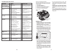
KEY PART
NO. NO. DESCRIPTION
KEY PART
NO. NO. DESCRIPTION
NOTE: All component dimensions given in U.S. inches
1 inch = 25.4 mm
- - 532 43 61-44 SERVICE KIT, TRANSAXLE
1 532 43 64-98 WHEEL ASM (REAR)
2 532 12 17-48 WASHER, 16 GA.
3 812 00 00-01 E-CLIP
4 532 12 35-83 KEY. SQUARE
5 532 42 79-39 WELDMENT. DRIVE AXLE
6 532 42 80-69 CHAIN DRIVE
7 532 42 78-73 SPROCKET. 9 TOOTH
SPLINED
8 812 10 00-09 RING, SNAP
10 532 42 88-76 DIFFERENTIAL ASM
11 532 00 13-70 WASHER, THRUST
12 532 43 06-45 CHAIN, PRIMARY DRIVE
13 532 43 08-45 BUSHING
14 532 43 85-68 BRACKET, CARRIER
15 532 12 47-93 BEARING ASM
16 532 42 79-26 SHAFT INPUT
17 532 43 72-81 WHEEL, FRICTION A5M
18 532 42 47-59 ARM, SHIFT
19 532 43 08-70 ROD, BYPASS
20 532 42 79-97 BRACE CARRIER REAR
21 532 42 80-77 SPRING, CARRIER
22 532 42 80-76 SPRING, BRAKE
23 532 43 13-74 SPRING, BYPASS
24 532 42 79-95 BRACE CARRIER BOX
25 532 42 83-03 LINK, SHIFT
26 532 42 98-16 ARM. CLUTCH
27 532 42 90-53 WELDMENT SHIFT LEVER
28 532 42 83-02 SUPPORT, SHIFT LEVER
29 532 17 48-40 WASHER, NYLON
30 532 18 39-00 HUB SHIFT LEVER
31 532 42 90-55 SPACER, NYLON
32 532 42 84-64 MNTG BRKT. SHIFT ARM
33 532 42 84-61 BRACKET, SHIFTER FLEX
34 532 42 84-62 TUBE SHIFT ARM
35 532 41 15-55 GRIP, HANDLE
36 872 11 04-06 BOLT, CARRIAGE - 114-20 X 3/4
37 873 80 04-00 NUT NYLON LOCK 114-20
38 532 16 54-92 BOLT, SHOULDER
39 874 78 04-12 BOLT, 1/4-20 X 3/4
40 810 04 04-00 WASHER, LOCK
41 819 09 12-10 WASHER FLAT
42 532 16 60-02 WASHER, SERRATED
43 873 68 04-00 NUT, CROWN LOCK 114-20
45 817 49 04-36 SCREW 1/4-20 X 2 114
46 819 09 10-16 WASHER
47 817 49 04-20 SCREW, 1/4-20 X 1 1/2
48 532 43 02-49 PLATE BRAKE ANTI - ROTATE
49 532 43 02-45 SPRING, BRAKE RETURN
50 532 42 80-21 ARM, BRAKE
51 532 43 02-47 SPACER RETURN
52 532 42 80-78 CALIPER, BRAKE ASM
53 877 01 08-10 PIN, DOWEL 1/4
54 532 42 80-19 PLATE, BRAKE PAD
55 532 42 80-17 PUCK BRAKE
56 532 43 52-53 ROTOR, BRAKE
57 532 42 80-16 CAP, BRAKE CALIPER
58 532 12 47-88 PIN, RETAINER
59 817 49 05-08 BOLT, 5/16-16 X 112
60 532 44 08-55 CABLE, BRAKE
61 532 42 79-45 WELDMENT, PEDAL
62 532 42 96-78 ROD, PARKING BRAKE
63 877 10 08-12 PIN, .25 X .75 CLEVIS
64 532 42 10-76 PIN, COTTER 5/64 X 3/4
65 532 42 93-25 BRACKET, BRAKE SUPPORT
66 532 42 96-94 COVER PEDAL
67 532 42 96-93 COVER, BRAKE PEDAL
68 817 49 04-06 SCREW, 1/4-20 X 3/8
69 532 42 80-70 BRAKE CABLE MOUNT
70 817 00 05-12 BOLT, 5/16-18 X 3/4
71 532 43 64-99 CAP HUB AXLE
72 812 00 00-02 E RING #5133-62
73 532 42 95-19 SPROCKET II TOOTH
SPLINED
74 532 43 78-41 TENSION LRV CHAIN
75 532 43 34-95 SPROCKET IDLER
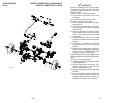
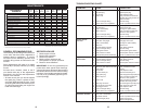
RIDING MOWER MODEL NUMBER WE261 (96022000801)
DRIVE
PRODUCT NUMBER 960 22 00-08


