


20
SERVICE AND ADJUSTMENTS
WARNING: TO AVOID SERIOUS INJURY, BEFORE PERFORMING ANY
SER VICE OR AD JUST MENTS:
1. Depress clutch/brake pedal fully and set parking brake.
2. Place motion control lever in neutral (N) position.
3. Place deck clutch in “DISENGAGED” position.
4. Turn ignition key to “STOP” and remove key.
5. Make sure the blade and all moving parts have completely stopped.
6. Disconnect spark plug wire from spark plug and place wire where it cannot
come in contact with plug.
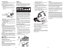
RIDING MOWER
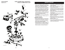
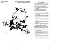
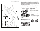
TO REMOVE MOWER
1. Place deck clutch in “DISENGAGED"
position.
2. Move mower height adjustment lift lever
forward to low er mower to its lowest
po si tion.
3. Remove mandrel cover.
4. Remove pins holding left and right front
mower suspension arms in place.
5. Remove bolt holding deck front to rear
leveling rod in place.
TO INSTALL MOWER
Install in reverse order following instructions
in "TO REMOVE MOWER" section.
6. Remove pin holding deck lift link arm in
place.
7. Remove bolt holding deck side to side
leveling rod in place.
8. Remove belt from around pulleys.
9. Slide deck out from under side of mower.
Deck Leveling
Side to Side
Rod Bolt
Mandrel Cover
Deck Lift
Link Pin
Front Leveling
Rod Bolt
Mower
Suspension
Arm Pin
21
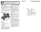
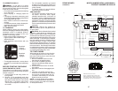
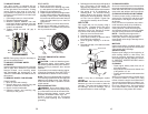
TO LEVEL MOWER HOUSING
Adjust the mower while riding mower is
parked on level ground or driveway. Make
sure tires are properly inflated (See side
of tire for proper PSI). If tires are over or
underinflated, you will not properly adjust
your mower.
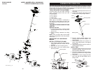
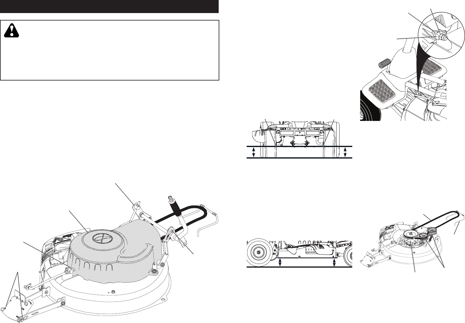
SIDE-TO-SIDE ADJUSTMENT
• Raise mower to its highest position.
• Measure dis tance "A" from bot tom edge
of mower to ground level at front corners
of mower.
• To raise the right side of the mower, tighten
lift link adjustment nut.
• To lower the right side of the mower, loosen
lift link adjustment nut.
NOTE: Each full turn of adjustment nut will
change mower height about 3/16".
A
A
Bottom Edge of
Mower to Ground
Bottom Edge of
Mower to Ground
• Recheck measurements after ad just ing.
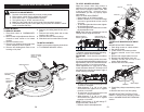
FRONT-TO-BACK ADJUSTMENT
IMPORTANT: Deck must be level side-to
side.
To obtain the best cutting results, the mower
housing should be adjusted so that the front is
approximately 1/8" to 1/2" lower than the rear
when the mower is in its highest position.
Check adjustment on right side of riding
mower. Measure dis tance “F” directly in front
and behind the mandrel at bottom edge of
mower housing as shown.
F
F
• To lower front of mower housing turn nuts
“G” and “H” clockwise.
• When distance “F” is 1/8" to 1/2" lower
at front than rear, tighten nut “H” against
trunnion on front link.
• To raise front of mower housing turn nuts
“G” and “H” counter clockwise.
• When distance “F” is 1/8" to 1/2" lower
at front than rear, tighten nut “H” against
trun nion on front link.
NOTE: Each full turn of "G" will change "F"
by approximately about 3/8".
• Recheck side-to-side adjustment.
Nut "G"
Nut "H"
Trunnion
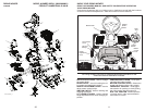
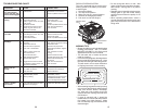
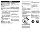
TO REPLACE MOWER BLADE DRIVE
BELT
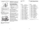
MOWER DRIVE BELT REMOVAL
1. Park riding mower on a level surface.
2. Set parking brake.
3. Lower mower to its lowest position.
4. Remove mandrel cover from mower
deck.
5. Remove rear engine plate from unit.
6. Remove rear belt keeper from unit.
7. Carefully roll belt over the top of the
mower blade mandrel.
8. Remove belt from idler pulleys.
Belt
Keeper
Mandrel
Mower Drive Belt
Idler Pulleys
9. Check idler pulleys to see that they rotate
freely.
10. Remove belt from rear drive pulley.
MOWER DRIVE BELT INSTALLATION
Install in reverse order following instruc-
tions in "MOWER DRIVE BELT REMOVAL"
section.