


34
10
11
2
2
31
6
6
7
7
9
31
9
1
2
30
3
1
2
30
3
4
4
5
29
8
8
8
12
13
14
15
16
17
18
19
19
20
21
22
28
23
24
25
26
27
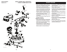
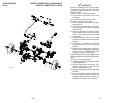
LRV-A_Steering_1_r4
RIDING MOWER MODEL NUMBER WE261 (96022000801)
STEERING
PRODUCT NUMBER 960 22 00-08
7
Your new riding mower has been assembled at the factory with the exception of those
parts left unassembled for shipping purposes. To ensure safe and proper operation of your
riding mower all parts and hardware you as sem ble must be tightened securely. Use the
correct tools as nec es sary to in sure proper tightness.
ASSEMBLY/PRE-OPERATION
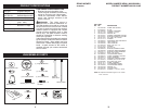
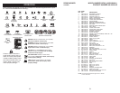
TOOLS REQUIRED FOR ASSEMBLY
A socket wrench set will make assembly
easier. Stan dard wrench sizes you need
are listed below.
(1) 3/4" wrench
(1) 1/2" wrench
(1) Utility knife
(1) Tire pressure gauge
When right or left hand is mentioned in
this man ual, it means when you are in the
operating po si tion (seated be hind the steer-
ing wheel).
TO REMOVE RIDING MOWER FROM
CARTON
UNPACK CARTON
1. Cut along dotted lines on all four panels
of carton. Remove carton and top frame
as one unit.
2. Remove packing materials from riding
mower.
NOTE:
Only cut carton with a short blade
utility knife, a long blade or saw can puncture
tires on unit.
HOW TO SET UP YOUR RIDING
MOWER
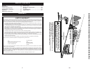
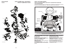
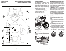
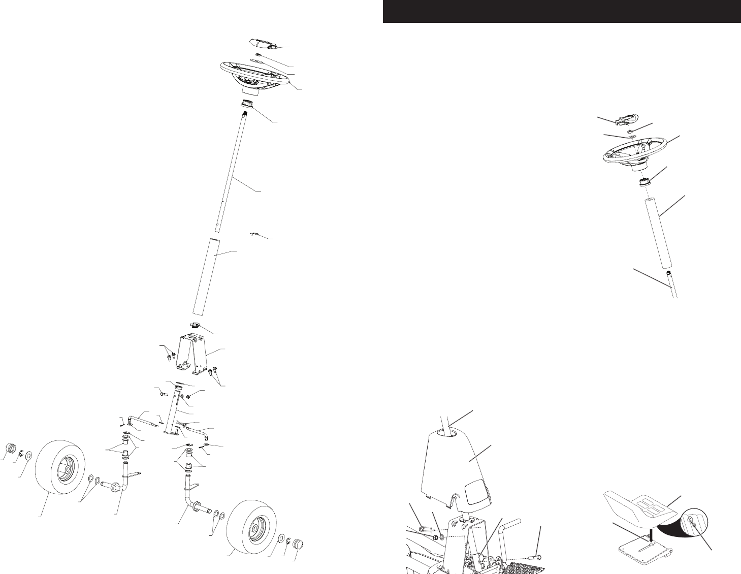
INSTALL STEERING COLUMN
1. Insert steering shaft into mount and se-
curely fasten with bolt, washer, and nut
provided.
2. Insert pin into hole in steering shaft.
3. Slide plastic cover over steering shaft
and into position.
4. Slide steering shaft protective foam cover
over shaft.
5. Position front wheels of the riding mower
so they are pointing straight forward.
Plastic Cover
Steering
Shaft
Mount
Nut
Washer
Pin
Bolt
Steering Shaft
Foam Cover
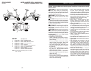
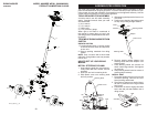
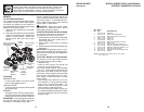
Steering Wheel
Adapter
Insert
Washer
Nut
Steering Shaft
6. Remove steering wheel adapter from
steering wheel and slide adapter onto
steer ing shaft.
7. Press steering wheel into position on
shaft, install large washer, and tighten
nut securely.
8. Snap steering wheel insert into center of
steer ing wheel securely.
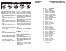
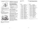
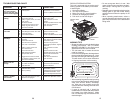
INSTALL SEAT
1. Pivot seat upward and remove from the
cardboard packing. Remove the card-
board packing and discard.
2. Place seat on seat pan so head of shoul-
der bolt is positioned over large slotted
hole in pan.
3. Push down on seat to engage shoulder
bolt in slot and pull seat towards rear of
riding mower.
0
24
6
6
Seat Pan
Shoulder
Bolt
Seat