


Operating Instructions
38
ADJUSTING CUTTING HEIGHT
WARNING
The engine must be stopped before ad-
justing cutting height. Disengage the blade
clutch (PTO), stop the engine, and remove
the ignition key. Wait for all move ment to
stop before getting off the seat.
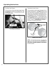
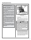
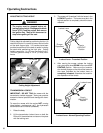
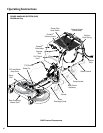
Cutting height is adjusted by positioning the four (4)
re tainer hitch pins in a series of seven vertical holes
on the deck support pins. Lift handles have been
pro vided on each end of the deck to assist in raising
the deck while positioning the hitch pins. Cutting
heights range from 1 in. (25 mm) [top holes] to 4 in.
(102 mm) [bottom holes] in 1/2 in. (13 mm) incre-
ments.
Lift Handle
Deck Support
Pin
Hitch Pin
Cutting Height Adjustment
TRANSMISSION LOCKOUT
IMPORTANT: DO NOT TOW this mower with the
transmission lockout engaged. Towing can produce
excessive internal pressure and damage the trans-
mission.
To move the mower with the engine NOT running
(dead battery, maintenance, etc.), the hydrostatic
transmissions are unlocked (released).
1. Raise the body.
2. Lift the transmission lockout lever on both the
RH and LH transmissions and secure into place
with the locking cam.
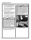
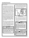
3. The mower will “freewheel” with the levers in the
LOCKOUT position. The levers must be in the
highest position to completely unlock the trans-
missions.
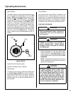
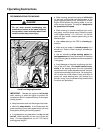
Lockout Lever
Plunger
Depressed
Cam in
LOCKOUT
Position
Lockout Lever - Freewheel Position
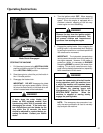
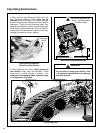
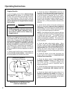
4. After moving the mower, release the locking
cam, placing the lever DOWN in the normal OP-
ERATING position. Make sure the transmis-
sion lockout plunger on the side of the transmis-
sion case (activated by the lockout lever) is
com pletely released, otherwise the transmis-
sion operation will be erratic.
Lockout Lever
Plunger
Released
Cam in
UNLOCKED
Position
Lockout Lever - Normal Operating Position