


Maintenance Instructions ELECTRICAL SYSTEM
83
ELECTRICAL SYSTEM
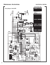
For troubleshooting, refer to Wiring Diagram.
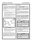
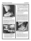
IMPORTANT: Disconnect both battery cables be-
fore unplugging any wiring connectors or making re-
pairs on the electrical system.
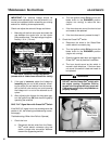
IMPORTANT: Disconnect the battery cables before
unplugging and removing the instrument panel.
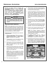
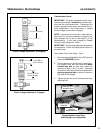
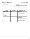
Circuit Breakers
Location Reset Amperage Circuits (Electrical Load)
Master Circuit Breaker
Mounted on Bracket Behind
Battery
40 AMP - Instrument Panel
- Starter Solenoid
- Glow Plugs
- Pull Circuit, Fuel Valve Solenoid
Radiator Fan Circuit Breaker
Mounted Adjacent to Master
Circuit Breaker
30 AMP - Cooling Fan
- Cooling Fan Module
Instrument Panel 7 AMP - Time Delay Module
- Panel Gauges
- Warning Lights/Horn
- Powerfil
®
Motor & Full Signal Horn
Instrument Panel 10 AMP - Headlights
- Safety Switch Relays
- Hold Circuit, Fuel Valve Solenoid
- Fuel Pump