


71
Maintenance Instructions
REPLACING/REPAIRING/
ADJUSTMENTS
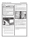
Reinstall the blades following procedure in CHECK-
ING/SERVICING for Sharpen Mower Blades in-
structions. If blades are replaced, always use Walk-
er original equipment blades to ensure safety and
optimum performance. The quality and performance
of replacement blades offered by other manufac-
turers cannot be guaranteed, they could be dan-
gerous.
CAUTION
ALWAYS use genuine factory replace-
ment parts. Substitute parts CAN result
in product malfunction and possible in-
jury to the operator.
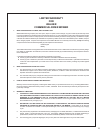
ADJUSTMENTS
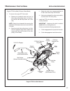
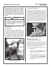
Steering Handles
An adjustment range of approximately 3 in.
(76.2 mm) is available on the steering handles - the
handles can be adjusted forward or aft depending
on the arm length of the operator. The handles can
be adjusted by loosening the locknut at the pivot
point and the locknut holding the handle in position
in the adjustment slide. Adjust handles into the most
comfortable position and tighten both locknuts.
Adjustment
Slide
Locknut
(Position)
Locknut
(Pivot Point)
Steering Handle Adjustment
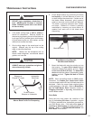
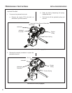
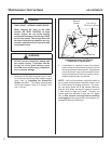
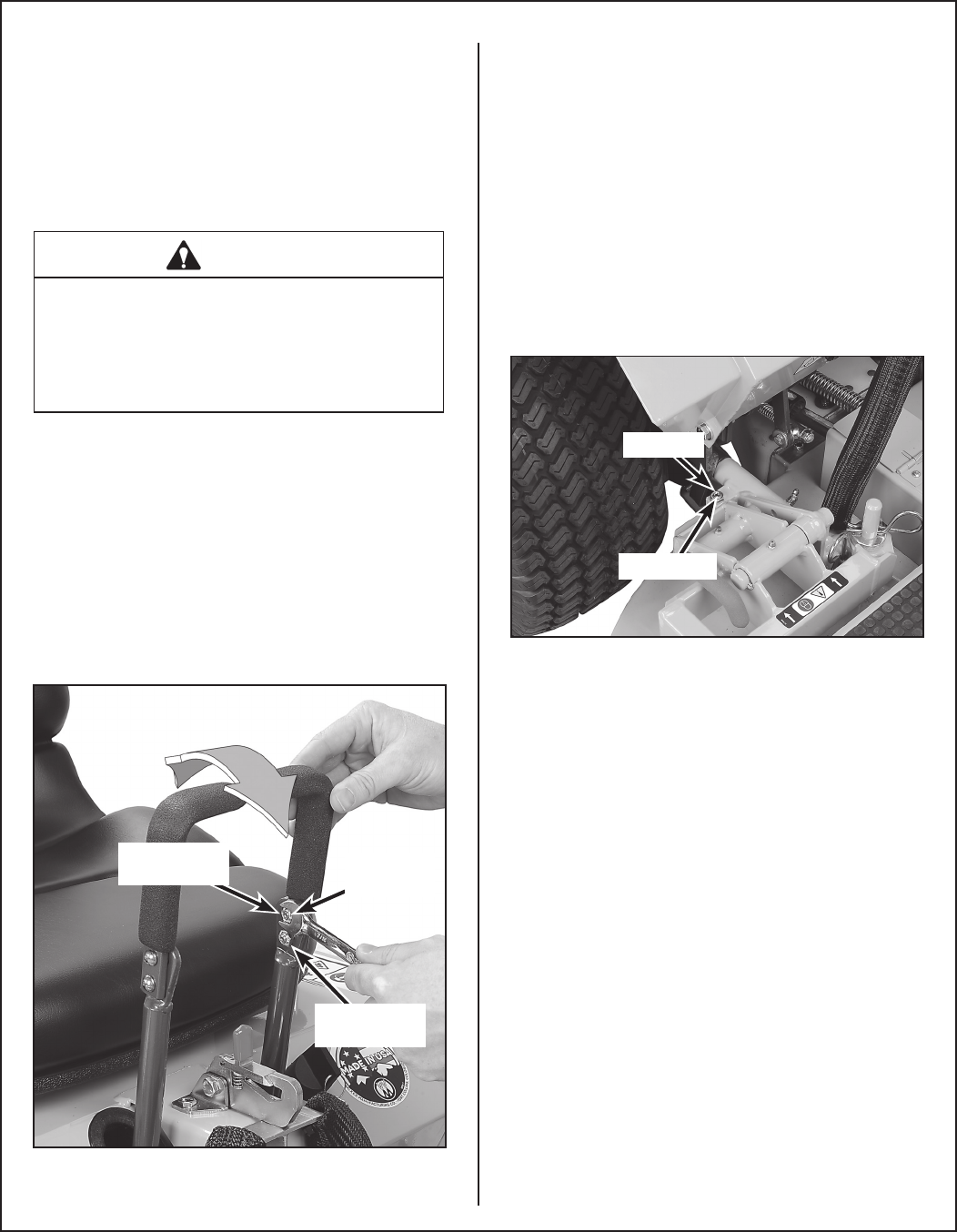
Tilt-Up Deck Adjustable Stop
When the carrier frame hinge joint is properly ad-
justed, the deck lock levers should move in and out
of the engaged and disengaged positions freely. All
four (4) hitch pins used for height adjustment should
sit ush on the washers above the deck pin bushing.
On a level surface, if any pin is sticking up (likely the
front pins), tighten the opposite side or loosen the
same side to lower the pin. Adjustments are made
by loosening the jam nut and tightening or loosening
the set screws on the Deck Mount Pivot Brackets.
Retighten the jam nut when the adjustment is com-
plete.
Jam Nut
Set Screw
Tilt-Up Deck Adjustable Stop
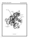
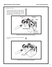
GHS Signal Horn Adjustment
(When Horn Sounds at Wrong Time)
The vertical position of the Grass-Pak
®
switch is
critical to make sure the catcher box does not over-
ll causing the delivery chute to clog. The vertical
position can be adjusted by moving the aluminum
shaft and vane on the Grass-Pak
®
switch.
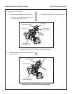
1. Position the discharge chute so that it is point-
ing straight back.
a. Turn the ignition switch ON and move the
blade clutch to the ENGAGED position
(engine not running).
b. Open the catcher back door and monitor
the spout position (as it oscillates) and
move the blade clutch to the DISENGAGED
position and turn the ignition switch to the
OFF position.