


Assembly Instructions
22
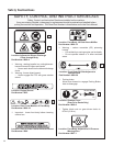
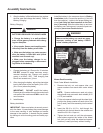
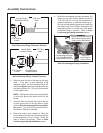
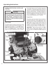
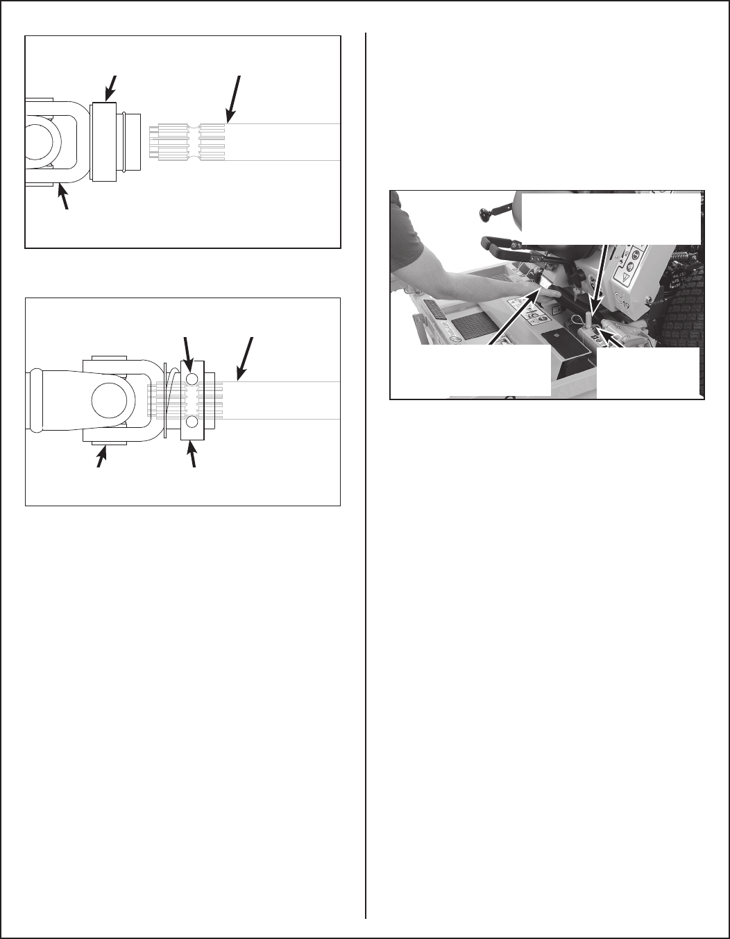
Coupler Ring in
Released Position
PTO Drive
Shaft
PTO Coupler
U-Joint
Quick Disconnect Ring “Released” Position
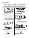
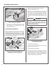
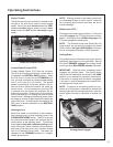
Coupler Ring in
Locked Position
PTO Drive
Shaft
PTO Coupler
U-Joint
Internal Balls
Locked on Shaft
Quick Disconnect Ring “Locked” Position
6. Slide the deck the rest of the way on the deck
arms. If the deck is rear discharge (GHS
equipped model), the rear discharge chute will
need to be aligned and connected to the blower
inlet during the last 2 in. (51 mm) of slide action
on the support arms.
NOTE: Raising the mower body may be helpful
in tting and guiding the deck chute into the
blower.
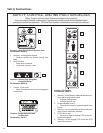
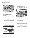
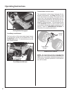
7. Install the hitch pin through the hole on the end
of each support arm to lock the deck in place
(refer to Deck Counterweight Spring Installa-
tion photo). Two (2) hitch pins are included in
the Owner’s Packet of materials.
8. Raise the mower body (instead of lifting the
front of deck) and clip the counterweight springs
to the receptacle on front of body. Lower the
body to tension the springs. (Refer to Deck
Counterweight Spring Installation photo.)
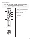
9. With the counterweight springs connected, the
weight on the deck caster wheels should be
15 to 25 Ib (6.8 to 11.3 kg); this adjustment is
preset at the factory. If required, the spring ten-
sion can be adjusted by tightening or loosening
the elastic stop nuts located underneath the
lower spring hook, or contact your local dealer
if additional help is required. Refer to Deck
Counterweight Spring Installation photo.
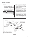
Spring Tension Adjustment
Nut Located Under Lower
Spring Hook (Not Visible)
Hitch Pins
Lock Deck On
Support Arms
Counterweight Springs
Clip Onto Body With
Forward Body Tilted Up
Deck Counterweight Spring Installation