


8
MAINTENANCE AND REPAIR INSTRUCTIONS
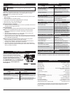
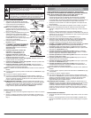
CHECKING THE OIL LEVEL
The importance of checking and maintaining the
proper oil level in the crankcase cannot be
overemphasized. Check oil before each use:
1. Stop the engine and allow oil to drain into
the crankcase.
2. Place the engine on a flat, level surface with
the cutting head shield hanging off a work
bench or table to get a proper oil level
reading (Fig. 23).
3. Keep dirt, grass clippings and other debris
out of the engine. Clean the area around the
dipstick before removing it.
4. Remove the oil fill plug (Fig. 25).
5. Look into the oil fill hole, use a flashlight if
needed. The oil should be just touching the
inner most thread (Fig. 24).
6. If the oil level is not touching the inner most
thread on the oil fill hole, add a small
amount of oil to the oil fill hole and recheck
(Fig. 24). Repeat this procedure until the oil
level reaches the inner most thread on the
oil fill hole.
NOTE: Do not overfill the unit.
NOTE: Make sure the O-ring is in place on the
oil fill plug when checking and changing the
oil (Fig. 25).
CHANGING THE OIL
Change the oil while the engine is still warm. The
oil will flow freely and carry away more impurities.
1. Unplug spark plug boot to prevent
accidental starting.
2. Remove the oil fill plug.
3. Pour the oil out of the oil fill hole and into a
container by tipping the unit to a vertical
position (Fig. 26). Allow ample time for
complete drainage.
4. Wipe up any oil residue on the unit and
clean up any oil that may have spilled.
Dispose of the oil according to federal, state
and local regulations.
5. Refill the crankcase with 3.04 fluid ounce
(90 ml) of SAE 30 SF, SG, SH oil (Fig. 28).
NOTE: Use the bottle and spout saved from
initial use to measure the correct amount of oil. The top of the label on
the bottle measures approximately 3.04 ounces (90 ml) (Fig. 29). Check
the level, See Checking the Oil Level. If the level is low, add a small
amount of oil and recheck. Do not overfill (Fig. 24).
6. Replace the oil fill plug.
7. Reconnect the spark plug boot.
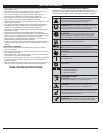
MAINTENANCE SCHEDULE
Perform these required maintenance procedures at the frequency stated in
the table. These procedures should also be a part of any seasonal tune-up.
NOTE: Some maintenance procedures may require special tools or skills. If
you are unsure about these procedures take your unit to any non-road
engine repair establishment, individual or authorized service dealer.
NOTE: Maintenance, replacement, or repair of the emission control devices
and system may be performed by any non-road engine repair
establishment, individual or authorized service dealer.
NOTE: Please read the California/EPA statement that came with the unit for
a complete listing of terms and coverage for the emissions control
devices, such as the spark arrestor, muffler, carburetor, etc.
FREQUENCY MAINTENANCE REQUIRED SEE
Every 10 hours Clean and oil air filter p. 9
After 1st 10 hours Change oil p. 8
Every 25 hours
Change oil
Check rocker arm to valve clearance and adjust
Check spark plug condition and gap
p. 8
p. 9
p. 9
WARNING:
To prevent serious injury, never perform
maintenance or repairs with unit running. Always service and
repair a cool unit. Disconnect the spark plug wire to ensure that
the unit cannot start.
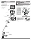
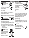
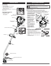
LINE INSTALLATION
Always use original equipment manufacturer
0.095 in. (2.41 mm) replacement line. Other types
of line may make the engine overheat or fail.
NOTE: There may be a need to remove the old
line prior to installing new line. If so, please
refer to Removing the old line or obstructions.
NOTE: Line installation DOES NOT require
removal or disassembly of the cutting head.
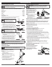
1. Align the arrows on the cutting head knob
with the outer spool eyelets, if they are not
already. (Fig. 16)
2. Using 10.5 ft. (3.2 m) of 0.095 in. (2.41 mm)
replacement line push an end of the line
through one of the eyelets until it protrudes
through the opposite side. Continue pushing or
pulling the line until the line is evenly distributed,
so approximately 5 ft. (1.5 m) is visible from
both sides of the cutting head. (Fig. 17)
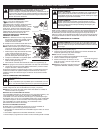
3. Hold the cutting head knob and turn the
cutting head counterclockwise to wind the
line around the spool until 5 in. (12.7 cm) is
protruding from each side of the cutting
head. (Fig. 18)
NOTE: If winding the line from a large spool of
line, cut the line from the spool so that it
measures 5” from the eyelet.
4. Start the unit and bump the cutting head on
the ground until the desired cutting length is
achieved.
REMOVING THE OLD LINE OR OBSTRUCTIONS
NOTE: There should only be a need to remove
the bump cap if the old line gets jammed or
an obstruction preventing the new line from
being installed properly.
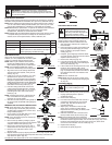
1. Firmly press in on the tabs that are on each
side of the cutting head. (Fig. 19)
NOTE: It may be easier to press in and then up
on one tab at a time.
2. Remove the cap either by letting it pop off
or a slight wiggle of the cap may be required
and pull it off the outer spool (Fig. 20).
3. Remove any old line from the inner reel or
obstructions from the outer spool. (Fig. 21)
4. Place the inner reel back into the outer
spool (Fig. 20).
5. Replace the bump cap by aligning the tabs of the bump cap with the tab
lock windows of the outer spool and press down firmly until both tabs
snap back into place. (Fig. 22)
To install new line, please refer to the Line Installation section.
WARNING:
To prevent extensive
engine wear and damage to the
unit, always maintain the proper oil
level in the crankcase. Never
operate the unit with a low oil level.
CAUTION:
Wear gloves to prevent
injury when handling the unit.
Fig. 17
Fig. 18
Fig. 19
Fig. 20
Bump
Cap
Inner
Reel
Spring
Outer
Spool
UP
Fig. 21 Fig. 22
Fig. 23
Fig. 24
PRESS
Max Oil Fill Line
Fig. 25
Fig. 26
Fig. 27
Fig. 28
Oil Fill Plug
O-Ring
Oil Fill Hole
Fill Line
Fig. 16
Cutting Head Knob
Arrow
Eyelet
Align
5 Feet
Tab