


2. Disconnect the spark plug wire.
3. Clean dirt from around the spark plug.
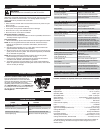
Remove the spark plug from the cylinder head
by turning a 5/8 in. socket counterclockwise.
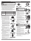
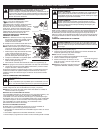
4. Remove the engine cover (Fig. 32).
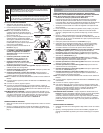
5. Clean dirt from around the rocker arm cover.
Remove the screw holding the rocker arm
cover with a large flat blade screwdriver or
Torx® T-25 bit (Fig. 33). Remove the rocker
arm cover and gasket.
6. Pull the starter rope slowly to bring the
piston to the top of its travel, (known as top
dead center). Check that:
• The piston is at the top of its travel while
looking in the spark plug hole (Fig. 33).
• Both rocker arms move freely, and both
valves are closed.
If these statements are not true, repeat this
step.
7. Slide the feeler gauge between the rocker arm and the valve return
spring. Measure the clearance between the valve stem and rocker arm
(Fig. 34). Measure both the intake and exhaust valves.
The recommended clearance for both intake and exhaust is .003 – .006 in.
(.076 – 0.152 mm). Use a standard automotive .005 in. (0.127 mm) feeler
gauge. The feeler gauge should slide between the rocker arm and valve
stem with a slight amount of resistance, without binding (Fig. 34 and 35).
8. If the clearance is not within specification:
a. Turn the adjusting nut using a 5/16 inch (8 mm) wrench or nut driver
(Fig. 35).
• To increase clearance, turn the adjusting nut counterclockwise.
• To decrease clearance, turn the adjusting nut clockwise.
b. Recheck both clearances, and adjust as necessary.
9. Reinstall the rocker arm cover using a new gasket. Torque the screw to
20–30 in•lb (2.2–3.4 N•m).
10. Check the spark plug and reinstall. See Replacing the Spark Plug.
11. Replace the spark plug wire.
12. Reinstall the engine cover. Check alignment of the cover before
tightening the screws. Tighten screws.
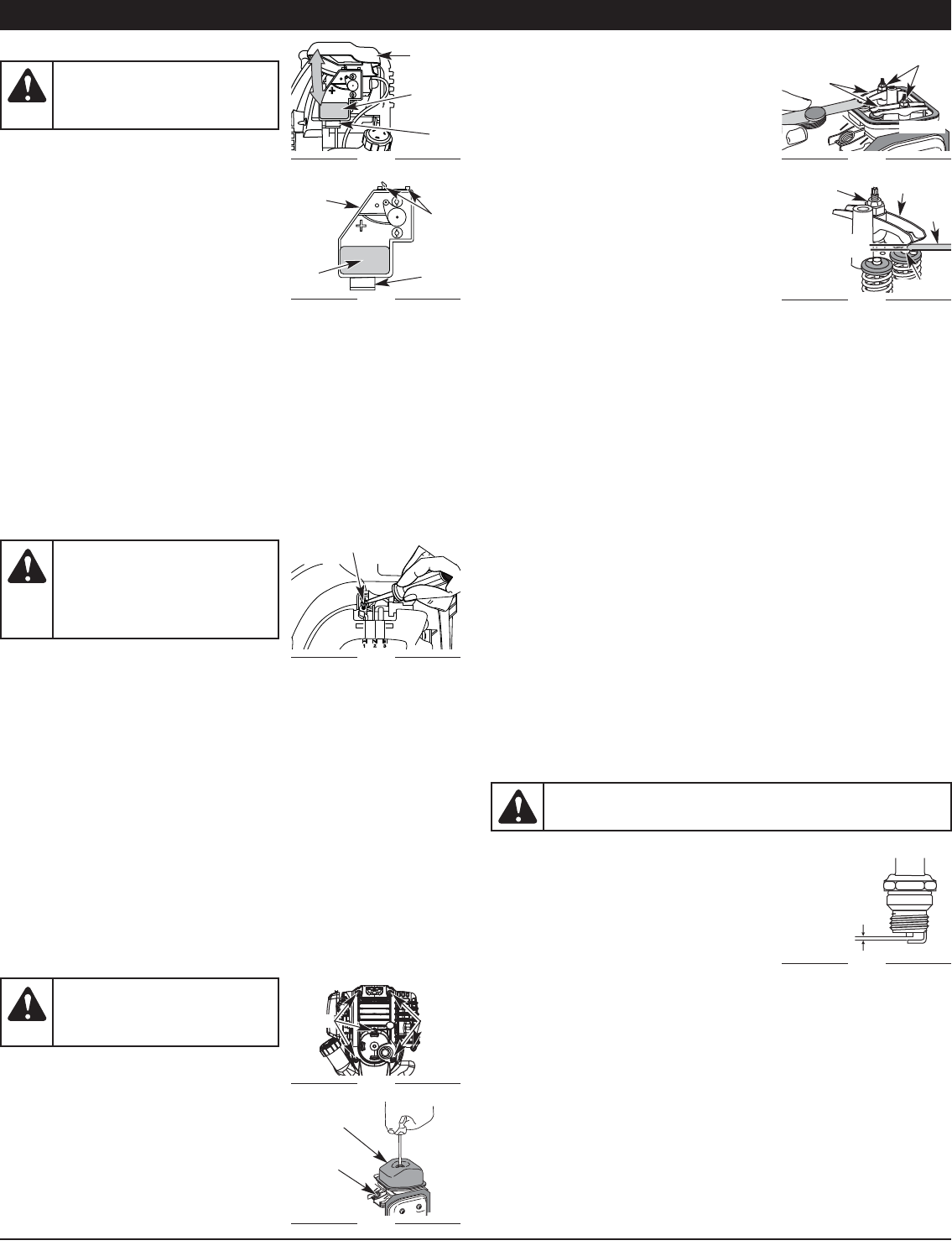
REPLACING THE SPARK PLUG
Use a replacement part number 753-05784 or Champion® RDZ4H spark
plug. The correct air gap is 0.025 in. (0.635 mm.).
1. Stop the engine and allow it to cool. Remove the six (6) screws on the back
of the engine cover with a Flat-head or T-25 Torx® screwdriver (Fig. 36).
2. Grasp the plug wire firmly and pull the cap from the spark plug.
3. Clean dirt from around the spark plug. Remove the spark plug from the
cylinder head by turning a 5/8 in. socket counterclockwise.
4. Replace cracked, fouled or dirty spark plug.
Set the air gap at 0.025 in. (0.635 mm.)
using a feeler gauge (Fig. 36).
5. Install a correctly-gapped spark plug in the
cylinder head. Turn the 5/8 in. socket
clockwise until snug.
If using a torque wrench torque to:
110-120 in.•lb. (12.3-13.5 N•m)
Do not over tighten.
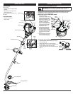
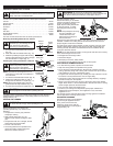
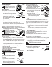
AIR FILTER MAINTENANCE
Cleaning the Air Filter
Failure to maintain your air filter properly can
result in poor performance or can cause
permanent damage to your engine.
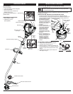
1. Open the air filter cover. Push the tab on the
under side of the cover inward. Then pull the
air filter cover out and up. (Fig. 29).
2. Remove the air filter (Fig. 30).
3. Wash the filter in detergent and water. Rinse
the filter thoroughly and allow it to dry.
4. Apply enough clean SAE 30 motor oil to
lightly coat the filter.
5. Squeeze the filter to spread and remove excess oil.
6. Replace the filter (Fig. 30).
NOTE: If the unit is operated without the air filter, you will VOID the warranty.
7. Reinstall the air filter cover. Position the slots on the top of the air filter
cover onto the tabs at the top of the back plate (Fig. 29).
8. Swing the cover down until the tab on the air filter backplate snaps into
place in the slot on the air filter cover (Fig. 29).
IDLE SPEED ADJUSTMENT
The idle speed of the engine is adjustable. An idle adjustment screw is
between the air filter cover and the engine starter housing (Fig. 31).
NOTE: Careless adjustments can seriously damage your unit. An authorized
service dealer should make carburetor adjustments.
If, after checking the fuel and cleaning the air
filter, the engine still will not idle, adjust the idle
speed screw as follows:
1. Start the engine and let it run at a high idle for a minute to warm up.
Refer to Starting and Stopping Instructions.
2. Release the throttle trigger and let the engine idle. If the engine stops,
insert a small phillips in between the air filter cover and the engine cover
(Fig. 31). Turn the idle speed screw in, clockwise, 1/8 of a turn at a time
(as needed) until the engine idles smoothly.
NOTE: The cutting attachment should not rotate when the engine idles.
3. If the cutting attachment rotates when the engine idles, turn the idle
speed screw counterclockwise 1/8 of a turn at a time (as needed), to
reduce idle speed.
Checking the fuel, cleaning the air filter, and adjusting the idle speed should
solve most engine problems. If not and all of the following are true:
• the engine will not idle
• the engine hesitates or stalls on acceleration
• there is a loss of engine power
Have the carburetor adjusted by an authorized service dealer.
ROCKER ARM CLEARANCE
This adjustment requires disassembly of the
engine. If you feel unsure or unqualified to
perform this, take the unit to an authorized
service center.
• The engine must be cold when checking or
adjusting the valve clearance.
• This task should be performed inside, in a
clean, dust free area.
1. Remove the six (6) screws on the back of
the engine cover with a Flat-head or T-25
Torx® screwdriver (Fig. 32).
MAINTENANCE AND REPAIR INSTRUCTIONS
WARNING:
To avoid serious
personal injury, always turn the unit
off and allow it to cool before you
clean or service it.
WARNING:
To avoid serious
personal injury, always turn the unit
off and allow it to cool before you
clean or service it.
WARNING:
Do not sand blast, scrape or clean electrodes. Grit
in the engine could damage the cylinder.
WARNING:
The cutting
attachment may spin during idle
speed adjustments. Wear protective
clothing and observe all safety
instructions to prevent serious
personal injury.
9
Fig. 29
Fig. 30
Fig. 31
Fig. 32
Air Filter
Cover
Air Filter
Tab
Tabs
Back
Plate
Locking
Tab
Air
Filter
Idle Adjustment Screw
View Of The Rear Engine Cover
Screws
Screws
Fig. 33
Fig. 34
Fig. 35
Fig. 36
Rocker Arm
Cover
Spark Plug
Hole
Adjustment
Nuts
Intake
Exhaust
Rocker
Arms
Valve Stem
Adjusting
Nut
Feeler
Gauge
Rocker Arm
0.003–0.006 in.
(0.076–0.152 mm)
0.025 in.
(0.635 mm)