


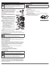
7
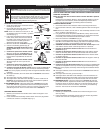
OPERATING INSTRUCTIONS
OPERATING THE EZ-LINK™ SYSTEM
The EZ-Link™ system enables the use of these optional Add-Ons:
Trimmer . . . . . . . . . . . . . . . . . . . . . . . . . . . . . . . . . . . . . . . . . . . . . . . . . AF720
Hedge Trimmer . . . . . . . . . . . . . . . . . . . . . . . . . . . . . . . . . . . . . . . . . . AH720
Brushcutter . . . . . . . . . . . . . . . . . . . . . . . . . . . . . . . . . . . . . . . . . . . . . BC720*
Cultivator . . . . . . . . . . . . . . . . . . . . . . . . . . . . . . . . . . . . . . . . . . . . . . . GC720
Edger . . . . . . . . . . . . . . . . . . . . . . . . . . . . . . . . . . . . . . . . . . . . . . . . . . . LE720
Pole Saw . . . . . . . . . . . . . . . . . . . . . . . . . . . . . . . . . . . . . . . . . . . . . . . PS720
Straight Shaft Trimmer . . . . . . . . . . . . . . . . . . . . . . . . . . . . . . . . . . . . . SS725
Turbo Blower . . . . . . . . . . . . . . . . . . . . . . . . . . . . . . . . . . . . . . . . . . . . TB720
*Do NOT use this attachment with an electric powered unit.
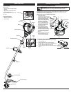
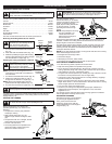
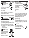
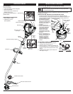
Removing the Cutting Attachment or Add-On
1. Turn the knob counterclockwise to loosen
(Fig. 12).
2. Press and hold the release button (Fig. 10).
3. While firmly holding the upper shaft housing,
pull the cutting attachment or add-on straight
out of the EZ-Link™ coupler (Fig. 11).
Installing the Cutting Attachment or Add-On
NOTE: Place the unit on the ground or on a
work bench to make add-on installation or
removal easier.
1. Turn knob counterclockwise to loosen (Fig. 12).
2. While firmly holding the add-on, push it
straight into the EZ-Link™ coupler (Fig. 11).
NOTE: Aligning the release button with the
guide recess will help installation (Fig. 10).
3. Turn the knob clockwise to tighten (Fig. 12).
For edging (when using the line head cutting attachment with EZ-Link™
models), lock the release button of the cutting attachment into the 90°
edging hole (Fig. 12).
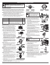
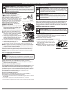
HOLDING THE TRIMMER
Before operating the unit, stand in the
operating position (Fig. 13). Check for the
following:
• The operator is wearing eye protection
and proper clothing
• With a slightly-bent right arm, the
operator’s right hand is holding the shaft
grip
• The operator’s left arm is straight, the left
hand holding the assist handle
• The unit is at waist level
• The cutting attachment is parallel to the
ground and easily contacts the grass
without the need to bend over
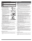
ADJUSTING TRIMMING LINE LENGTH
The Bump Head™ cutting
attachment allows you to release
trimming line without stopping the
engine. To release more line,
lightly tap the cutting attachment
on the ground (Fig. 14) while
operating the trimmer at high
speed.
NOTE: Always keep the trimming
line fully extended. Line
release becomes more
difficult as the cutting line
becomes shorter.
Each time the head is bumped, about 1 inch (25.4 mm) of trimming line is
released. A blade in the cutting attachment shield will cut the line to the
proper length if excess line is released.
For best results, tap the Bump Head™ on bare ground or hard soil. If line
release is attempted in tall grass, the engine may stall. Always keep the
trimming line fully extended. Line release becomes more difficult as the
cutting line becomes shorter.
NOTE: Do not rest the Bump Head™ on the ground while the unit is running.
Some line breakage will occur from:
• Entanglement with foreign matter
• Normal line fatigue
• Attempting to cut thick, stalky weeds
• Forcing the line into objects such as walls or fence posts
TIPS FOR BEST TRIMMING RESULTS
• For best trimming results, operate unit at full throttle.
• Keep the cutting attachment parallel to the ground.
• Do not force the cutting attachment. Allow the tip of the line to do the
cutting, especially along walls. Cutting with more than the tip will reduce
cutting efficiency and may overload the engine.
• Cut grass over 8 inches (200 mm) by working from top to bottom in small
increments to avoid premature line wear or engine drag.
• Cutting from right to left improves the unit's cutting efficiency. Clippings
are thrown away from the operator.
• Slowly move the trimmer into and out of the cutting area at the desired
height. Move either in a forward-backward or side-to-side motion. Cutting
shorter lengths produces the best results.
• Trim only when grass and weeds are dry.
• The life of your cutting line is dependent upon proper adherence of
explained trimming techniques, what vegetation is cut, and where
vegetation is cut.
For example, the line will wear faster when trimming against a foundation
wall as opposed to trimming around a tree.
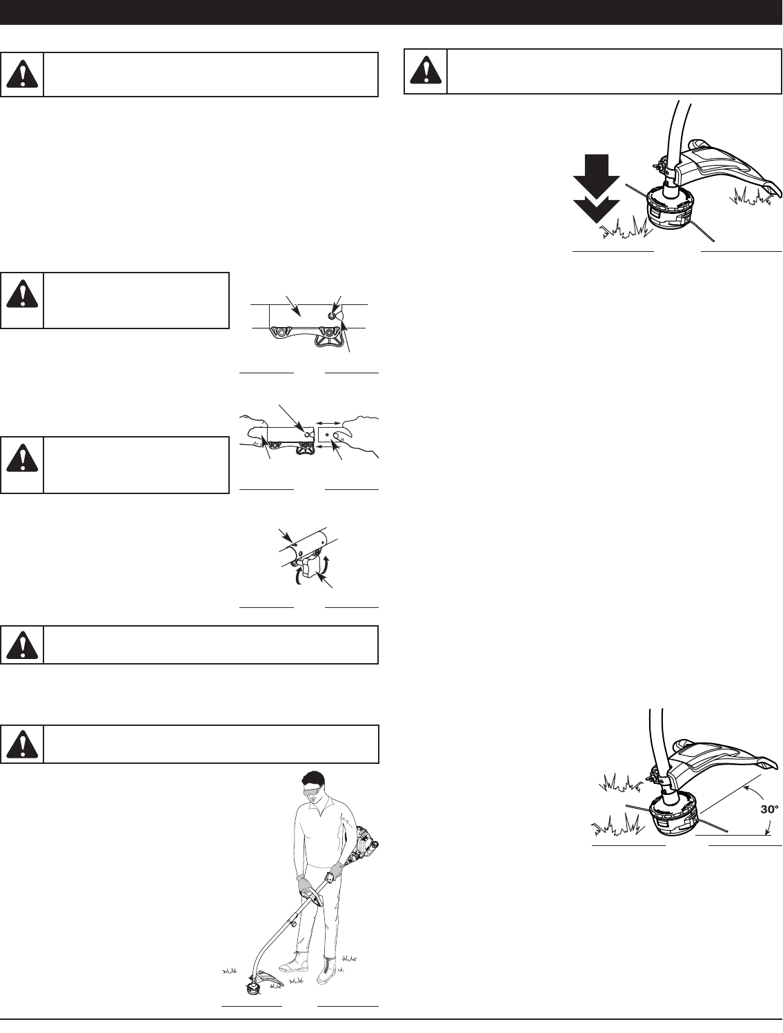
DECORATIVE TRIMMING
Decorative trimming is accomplished
by removing all vegetation around
trees, posts, fences and more.
Rotate the whole unit so that the
cutting attachment is at a 30° angle to
the ground (Fig. 15).
WARNING:
Before you begin using any attachment, read and
understand the manual that came with the attachment. Follow all
safety information contained within.
WARNING:
To avoid serious
personal injury and damage to the
unit, shut the unit off before
removing or installing add-ons.
CAUTION:
Lock the release button in the primary hole and
securely tighten the knob before operating this unit.
CAUTION:
Add-ons are to be
used in the primary hole only. Using
the wrong hole could lead to
personal injury or damage to the unit.
WARNING:
Always wear eye, hearing, foot and body protection
to reduce the risk of injury when operating this unit.
WARNING:
Do not remove or alter the line cutting blade
assembly. Excessive line length will make the clutch overheat. This
may lead to serious personal injury or damage to the unit.
Fig. 10
Fig. 11
Fig. 12
Guide Recess
Release
Button
EZ-Link™
Coupler
Upper Shaft
Housing
Lower Shaft
Housing
Primary Hole
Knob
90˚ Edging Hole
(Trimmer Only)
Fig. 13
Fig. 14
Fig. 15