


CONTROLS
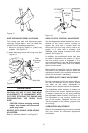
BLADE CONTROL HANDLE
WARNING: This con trol mech a nism
is a safety de vice. Never at tempt to
by pass its op er a tions.
The blade con trol han dle is lo cated on the
up per han dle of the mower. See Fig ure 1.
The blade con trol han dle must be de pressed
in or der to op er ate the unit. Re lease the
blade con trol han dle to stop the en gine and
blade.
WARNING: The blade will be ro tat -
ing when ever the en gine is run ning.
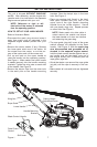
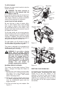
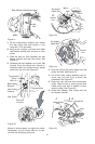
RECOIL STARTER
The recoil starter handle is attached to the
handle. See Figure 3. Stand behind the unit
in the operating position to start the unit.
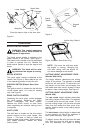
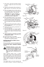
IGNITION SWITCH (Electric Start Units
Only)
The ignition switch is located on the left side
of the handle panel. It is used for starting
only. See Figure 4.
DRIVE CLUTCH CONTROL
Squeezing the drive clutch control engages
the drive system. Releasing the clutch
control disengages the drive system.
Release the clutch control to slow down
when negotiating an obstacle, making a turn
or stopping.
SHIFT LEVER
The shift lever is located on the drive clutch
control housing on the upper handle. See
Figure 1. This lever is used to select the
forward speed of the mower. When changing
your speed selection, release the drive
clutch control.
NOTE: Only move the shift le ver when
the en gine is run ning. Changing the
shift le ver set ting with the en gine off
can cause dam age to the mower.
CUTTING HEIGHT ADJUSTMENT LEVER
(Models: 959 & 979)
The height ad juster de ter mines the cut ting
height of the mower. The ad juster is lo cated
above the left rear wheel. To ad just the cut -
ting height, pull the le ver out and away from
the mower and then move it for ward or back
to se lect a new cut ting height. See Fig ure 5.
CUTTING HEIGHT ADJUSTMENT LEVER
(Model: 999)
The rear wheel height ad juster de ter mines
the cut ting height of the mower. The ad juster
is lo cated above the left rear wheel. To ad -
just the cut ting height, pull the le ver out and
away from the mower and then move it for -
ward or back to se lect a new cut ting height.
See Fig ure 5.
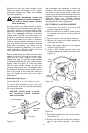
The front wheel cut ting height is de ter mined
by the se lec tion of one of six po si tions in
each caster as sem bly. See Fig ure 6.
To ad just, re move the wing nut from the axle
bolt. Slide the axle bolt and spring washer
from the as sem bly and se lect a cut ting
8
Fig ure 2
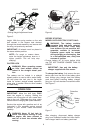
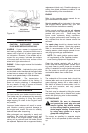
Carriage
Bolt
Wing Nut
Upper Hole
Place the hairpin clips in the inner hole.
Weld Pin
Lower Handle
Fig ure 4-(Elec tric Start Units Only)
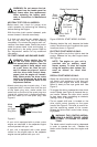
Ignition Key (Switch)
Fig ure 3
Rope
Guide
Recoil
Starter
Lower
Handle
Support
Rod