


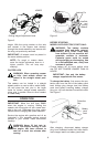
This unit is shipped WITHOUT GASOLINE
or OIL. After assembly, service engine with
gasoline and oil as instructed in the separate
engine manual packed with your unit.
NOTE: Reference to right or left
hand side of the mower is observed
from the operating position.
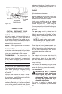
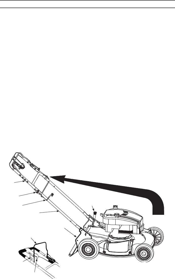
HOW TO SET-UP YOUR LAWN MOWER
Re fer to Il lus tra tion Be low
• Dis con nect the spark plug wire and move it
away from spark plug as in structed in the
sep a rate en gine man ual packed with your
unit.
• Re move the car ton in serts (if any). Re move
the loose parts which are in the car ton, lift
the mower from the car ton, or cut the cor -
ners of the car ton and roll the mower out.
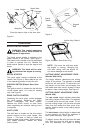
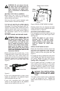
• Pull up and back on the up per han dle to
raise the han dle into the op er at ing po si tion.
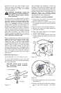
See Fig ure 1. Make cer tain the lower han dle
is seated se curely into the han dle mount ing
brack ets. Tighten the wing nuts on each side
of the han dle. See Fig ure 2.
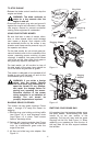
• Re move the hair pin clips from the outer hole
in the weld pins on the han dle mount ing
brack ets. Place the hair pin clips in the in ner
hole. See Fig ure 2.
• Place one car riage bolt (found in the hard -
ware pack in cluded with your unit) in the
up per hole of the right han dle mount ing
bracket from the in side out ward. Se cure
with one plas tic wing nuts. Re peat pro cess
on other side. See Fig ure 2.
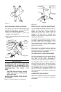
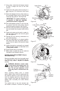
NOTE: Make cer tain the drive ca ble is
routed around the out side and above
the lower han dle so it does not in ter fere
with at tach ing the grass bag.
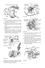
• The rope guide (pigs tail) is part of the grass
catcher sup port rod at tached to the lower
han dle. See Fig ure 3. With the spark plug
wire dis con nected and grounded as in -
structed in the sep a rate en gine man ual,
hold the blade con trol han dle against the up -
per han dle, and pull the starter rope out of
the en gine slowly un til it ex tends past the
rope guide (pigs tail).
• Guide the starter rope around the rope guide
(pig tail) un til the rope is se curely in the cen -
ter.
• Make cer tain all nuts and bolts are tight ened
se curely.
7
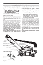
SET-UP INSTRUCTIONS
Fig ure 1
Upper
Handle
Rope Guide
Lower Handle
Cutting Height
Adjustment Lever
Wing Nut
Shift Lever
Drive Clutch
Control
Handle Mounting
Bracket
Blade Control Handle