


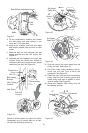
17. Using pli ers, ro tate the belt keeper bracket
so that it snaps into slot on the idler
bracket.
18. Tighten the idler pul ley bolt and locknut ½
turn us ing two 7/16" wrenches. See Fig ure
22.
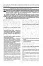
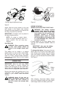
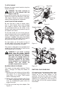
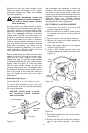
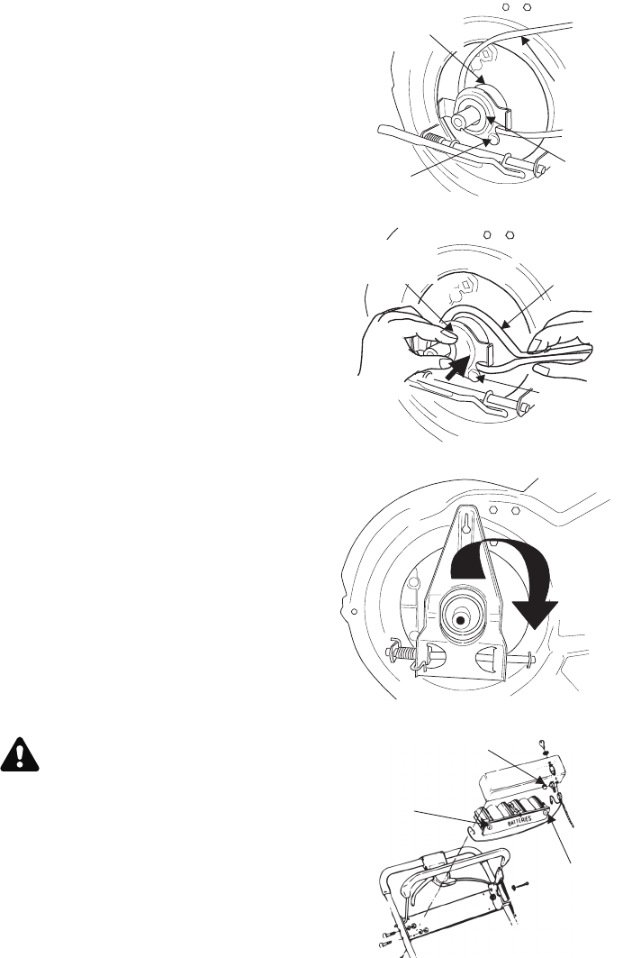
19. Place belt be tween the two pul ley halves on
the crank shaft. Make sure to route the belt
in side the belt guard pin. See Fig ure 26.
IM POR TANT: For proper as sem bly, it
is es sen tial to keep the as sem bly
po si tioned as shown in Figure 26.
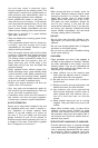
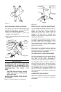
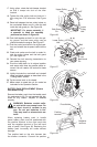
20. Pinch belt to gether so that it is not in the pul -
ley groove, and the lower pul ley can be
pushed to wards the en gine. See Fig ure 27.
21. Pivot the con trol arm back to its orig i nal po si -
tion and re in stall the six-speed ca ble into the
slot.
22. Check and make sure the belt is routed in -
side the pul ley halves and the belt guard
pin. See Fig ure 28.
23. Re in stall the bolt se cur ing trans mis sion to
rear mower hous ing.
24. Pivot the baf fle back to its orig i nal po si tion
and se cure with three hex screws ear lier re -
moved. You will need a 3/8" socket for these
screws.
25. Lightly lu bri cate the crank shaft and re in stall
blade and blade adapter as de scribed in the
“Cut ting Blade” sec tion.
26. Tip the mower back on its wheels.
27. Make cer tain to re test the unit for neu tral as
in structed in the Op er a tion Sec tion.
BATTERY PACK REPLACEMENT (Electric
start Models Only)
Re move the bat tery pack from the han dle panel
for re place ment only. Do not sep a rate the bat -
ter ies for any rea son. Dis pose of bat ter ies
prop erly.
WARNING: Bat teries con tain sul fu -
ric acid which may cause burns. Do
not short cir cuit or mu ti late in any
way. Do not put bat ter ies in fire.
They may burst or re lease toxic ma -
te rial.
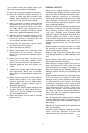
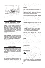
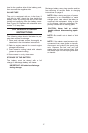
When re plac ing bat tery pack in han dle
panel, bat tery pack must be po si tioned with
the pos i tive ter mi nal to the right hand side
and the neg a tive ter mi nal to the left hand
side of panel. See Fig ure 29. Re placing the
bat tery pack in cor rectly will cause se ri ous
dam age.
The pos i tive lead on the wire har ness has
the smaller con nec tor. Con nect the pos i tive
16
Figure 26
Belt
Lower
Pulley
Half
Belt Guard
Pin
Upper Pulley
Half
Figure 27
Belt
Lower Pulley
Half
Belt Guard
Pin
Figure 28
Figure 29
Positive
terminal
Negative
terminal
Fuse Holder