


Section 2: Assembly
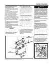
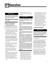
STEP 3 ATTACHING THE BATTERY
CABLES (MODEL F753B)
The positive battery terminal is marked
Pos. (+). The negative battery terminal is
marked Neg. (–).
The mower is shipped with the positive
(Red) cable secured to the positive ter-
minal (+) on the battery. Attach the
ground (Black) cable to the negative ter-
minal (–) on the battery, as follows:
1. Remove the plastic battery cover (G,
Figure. 2-3) by unthreading the two wing
nuts (H, Figure. 2-3) which secure it to
the battery hold-down rods (I, Figure. 2-
3)
2. Remove the hex bolt and hex nut
from the ground cable / heavy black wire
(E, Figure. 2-3).
3. Secure the ground cable to the nega-
tive battery terminal (–) with the bolt and
hex nut just removed.
4. Resecure the battery cover.
IMPORTANT:
• If the battery is put into service after
the date shown on top of battery,
charge the battery as instructed in the
Maintenence section of this manual
prior to operating the tiller.
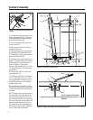
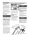
STEP 4: Attach Control Rods
A. Attach Wheel Drive Control Rod
1.
Locate the wheel drive control rod (F,
Figures 2-4A & 2-7) and remove the an-
gled end from the left handlebar by re-
moving the hairpin clip which secures it
to the Wheel Drive Control lever (V,
Figure 2-4A)
2. At left side of engine deck, insert
swivel block (H, Figures 2-4 & 2-5) on
wheel drive control rod into wheel drive
control arm (U, Figure 2-4).
3. Add a 5/16" washer (A, Figure 2-4)
and secure with a hairpin clip (B).
4. At upper end of control rod, re-insert
the angled end into the Wheel Drive
Control lever (V, Figure 2-4A) and re-
attach with hairpin clip (BB) removed
earlier.
B. Attach Operator Presence Control
Rod
1. Locate the Operator Presence Control
rod (E, Figures. 2-4 and 2-5)
. At bottom
of control rod, insert swivel block (G,
Figures 2-4 & 2-5) into control arm (T,
Figure 2-4).
2. Add one 5/16" washer and secure
with hairpin clip.
C. Attach Blade Drive Control Rod
1. Locate the blade drive control rod (C,
Figure 2-5). Insert one end of control rod
into blade drive bracket (D, Figure 2-5).
Add one 5/16" washer and attach with
hairpin clip (CC).
2. Insert the other end of rod into bot-
tom end of Blade Drive Control lever (J,
Figure 2-5). Add one 5/16" washer and
attach with hairpin clip (AA).
D. Attach and Adjust Gear Select Lever
NOTE: The retaining plate (N, Figure 2-5)
mentioned in the following steps is se-
cured to the rear of the mower with two
screws (O, Figure 2-5) and 1/4”-20 lock-
nuts. Remove the retaining plate and
save it, along with the two screws, be-
fore proceeding with assembly.
Control rods are adjusted at the fac-
tory and should not require additional
adjustment during assembly. After as-
sembling unit, control rod
adjustment should be checked (and
re-adjusted, if necessary) according to
information in Maintenance Section.
Failure to follow this instruction could
result in severe personal injury or
property damage.
WARNING
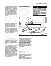
Figure 2-3: Connect wire terminals to battery terminals.
H
H
G
I
Red
(Positive Cable)
Black
(Negative Cable)
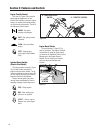
Figure 2-4: Left-hand control rods detail.
F
H
E
W
G
U
A, B
T
5