


Section 5: Maintenance
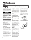
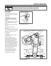
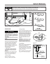
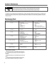
3. Slowly adjust at nut (O), if necessary,
until the distance between the back of
brake arm (N) and bracket (P) is 3/8”-
5/16". Use small adjustments (1/4 turn
maximum). NOTE: It may be necessary
to relieve spring tension when decreas-
ing distance. To do so, have an assis-
tant engage the Operator Presence
Control while you adjust the nut.
TRANSMISSION NEUTRAL
ADJUSTMENT
Follow this procedure to adjust neutral
on the transmission.
1. Stop engine, wait for all parts to
stop moving, and disconnect spark
plug wire.
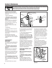
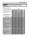
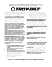
2. Rotate shift rod (I, Figures 5-14 and
5-15) clockwise until it stops in the neu-
tral (N) position (from forward gear
positions).
3. Hold down Operator Presence Control
(M, Figure 5-13) and push unit forward
and backward. Unit should move freely.
If not, continue with Step 4.
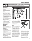
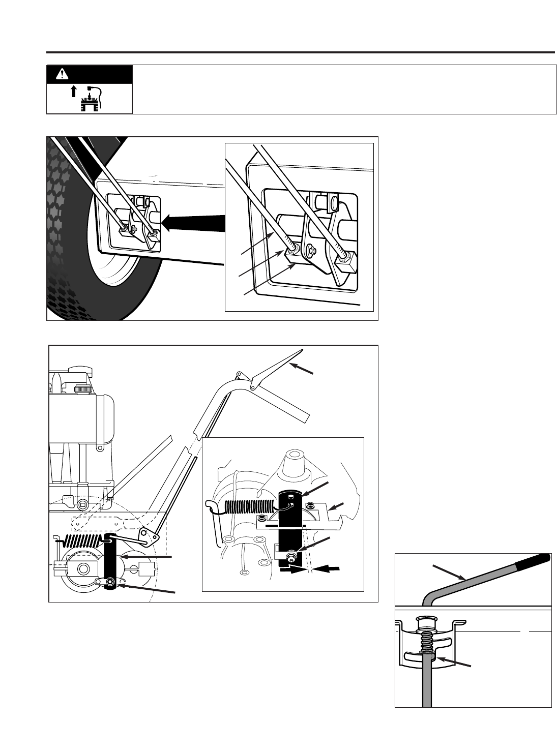
4. Remove cotter pin securing shift link
(P, Figure 5-15) to shift rod (I).
5. Move shift arm (X) back and forth as
necessary into each detent until trans-
mission is in neutral. NOTE: Moving
shift arm (X) clockwise all the way to the
left, and then one notch back counter-
clockwise, should put transmission into
neutral. When transmission is in neutral,
unit will move freely when pushed while
holding the Operator Presence Control
lever down. If transmission is NOT in
neutral, there will be a slight drag on the
wheels when pushing unit.
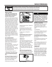
6. When shift arm (X) is in neutral posi-
tion, rotate shift link (P) until hooked
end fits back into hole in bottom end of
shift rod (I). NOTE: Shift rod (I) must be
held in the neutral position (see Figure
5-14) while shift link (P) is adjusted.
7. Secure shift link (P) into shift rod (I)
with cotter pin removed earlier.
8. Re-check neutral by pushing unit
back and forth and shifting lever (I) from
reverse to neutral. A small fine-tune
adjustment may be required.
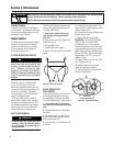
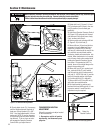
Figure 5-12: Wheel drive belt adjustment.
E
D
B
Figure 5-13: Wheel brake adjustment.
Figure 5-14: Lever in neutral (N) position.
M
N
O
N
O
P
I
Detent for
Neutral Position
3/8"-
5/16"
Before inspecting, cleaning or servicing the machine, shut off engine, wait for moving parts to stop, disconnect spark
plug wire and move wire away from spark plug. Remove ignition key (electric start models).
Failure to follow these instructions can result in serious personal injury or property damage.
WARNING
22