4
INTRODUCTION
Please carefully follow these assembly
steps to properly prepare your machine
for use. We recommend that you read
this Section in its entirety before begin-
ning assembly.
NOTE: All references to left, right, front
and rear of the machine are determined
by standing behind the handlebars and
facing the direction of forward travel.
INSPECTION AFTER DELIVERY
Inspect the shipping crate and machine
immediately after delivery. Make sure
neither the carton/crate nor the contents
have been damaged.
If you find or suspect any damage, con-
tact the carrier (trucking company)
immediately. Inform them of the specific
damage and that you wish to file a claim.
To protect your rights, be sure to put
this in writing to the carrier within 15
days. The carrier will let you know how
to proceed with your claim. Please let us
know if you need any assistance.
TOOLS/MATERIALS NEEDED:
• Wire Cutter
• Two 7/16” Wrenches
• 3/8” Wrench
• 1/2” Wrench
• Scissors or Pen Knife
• Needle-nose Pliers
• Tire Gauge
ASSEMBLY STEPS
STEP 1: Unpacking Mower
NOTE: LEFT and RIGHT sides of the unit
are as viewed from the operator’s posi-
tion behind the handlebars.
1. Cut straps, if present, securing unit
to pallet. Leave unit on pallet during as-
sembly (to safely remove unit from pal-
let, wait until you have completed as-
sembly steps 1-4).
2. Remove any protective packaging
from around the handlebars. Cut the
plastic tie straps holding the control rods
and struts to the handlebars.
STEP 2: Attach Handlebars
to Engine Deck
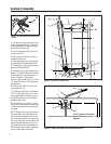
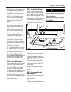
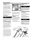
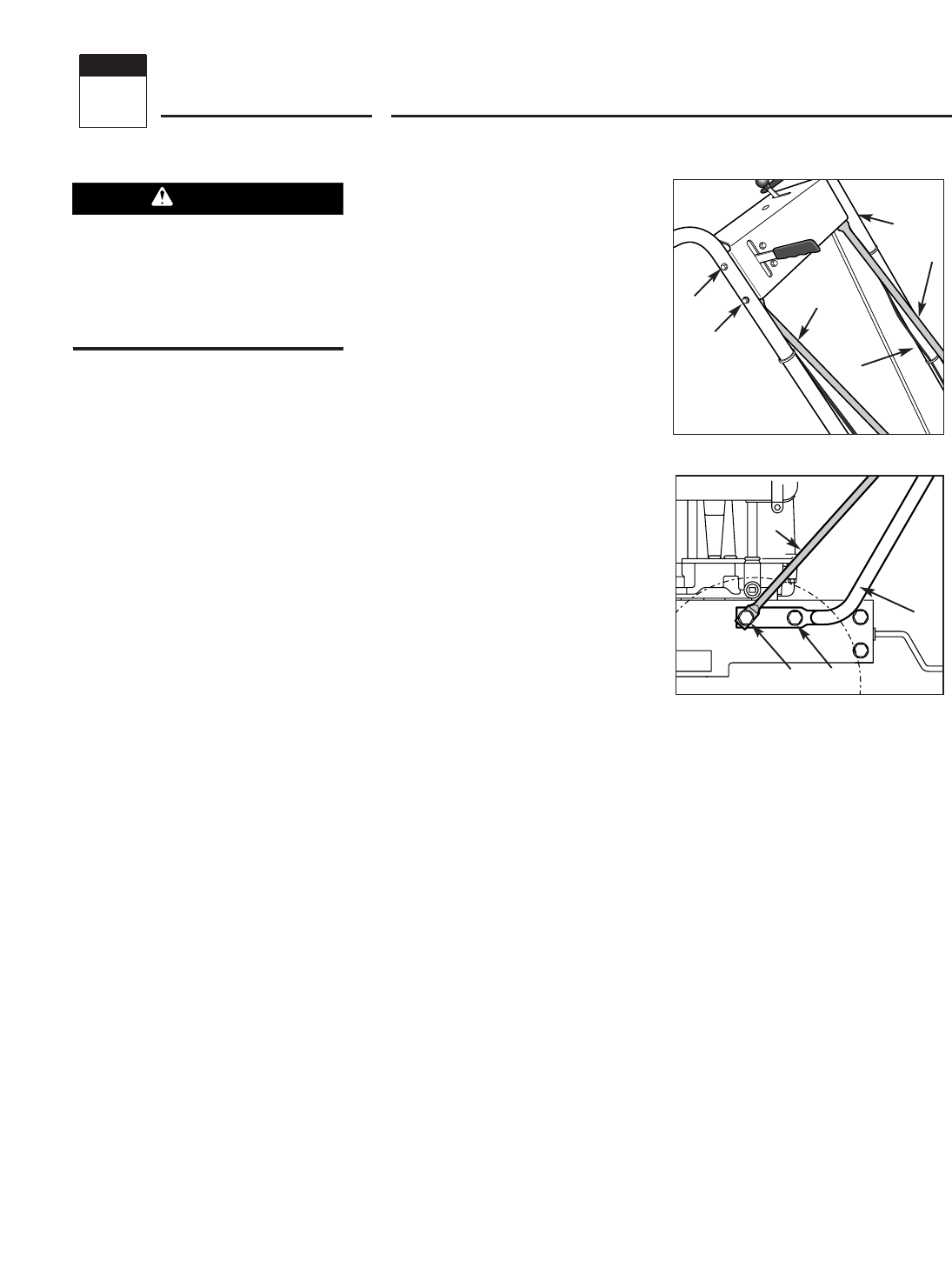
NOTE: Four screws (D, Figure 2-2) are
used to connect the handlebars to the
engine deck. At the factory, two of these
screws (front) are threaded directly into
lock nuts welded to the back sides of the
deck. The remaining two screws (rear)
secure the lower handle to the deck.
1. Remove and save the two 5/16"-18 x
3/4" screws (front) mentioned in the
NOTE above.
2. Loosen, but do NOT remove, the two
5/16"-18 x 3/4" screws (rear). Leave the
cardboard insert found between the left-
hand handlebar and engine deck, in
place.
3. Carefully pivot the handlebars over
the engine and position the handlebar
ends (E, Figure 2-2) against the sides of
the engine deck. Do not alloow the han-
dlebars to rub against the engine while
pivoting them.
4. Loosely secure the right-hand handle-
bar end to the deck by reinserting the
screw (D, Figure 2-2) removed earlier.
Do not secure the left-hand handle at
this point in assembly.
5. Remove the cardboard insert from
between the left-hand handlebar and
engine deck
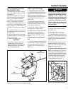
6. Remove the nut from the lower screw
(B, Figure 2-1) which secures the con-
sole to the handlebar on the left-hand
side of the unit.
7. Position a handlebar strut’s smaller
hole (A, Figure 2-1) over the screw (B,
Figure 2-1) on the INSIDE of the con-
sole, with the strut’s flat side against the
console.
8. Using the nut removed earlier, secure
the strut to the console/handlebar.
9. Align the loose end of the left-hand
handlebar strut (A, Figure 2-2) over the
front hole in the handlebar end. Secure
the strut and handlebar to the deck with
the 5/16"-18 x 3/4" screw (D, Figure 2-2)
removed earlier.
10. Remove the screw (front) that is
loosely securing the right-hand handle-
bar end to the deck. and repeat 6-9 on
the right-hand side of the unit.
11. On both sides of the unit, securely
tighten the screws (D, Figure 2-2) at the
lower ends of the handlebar before tight-
ening the screws (B & F, Figure 2-1) on
the console.
To prevent personal injury or property
damage, do not attempt to start the
engine until all assembly steps are
complete and you have read and
understand the safety, controls and
operating instructions in this manual.
WARNING
Figure 2-1
B
B
F
C
A
A
A
D
E
D
Figure 2-2: Attach handlebars and struts
to engine deck.
Assembly
2
Section


