


9
Section 3: Features and Controls
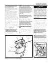
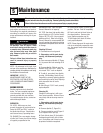
Gear Select Lever
Use this lever (C, Figure 3-1) to select
any of four forward ground speeds (1 -
Slow, 2 and 3 - Medium, 4 - Fast), N
(Neutral) and R (Reverse). The gear shift
pattern is shown in Figure 3-2.
To avoid damaging the transmis-
sion, do not shift gears when the
mower is moving.
For forward travel, use one of the four
numbered settings. To select reverse,
shift to neutral and then pull up on the
lever. Turn the lever to the R (reverse)
position and release the lever.
Put the lever in N (neutral) to manu-
ally push the mower and when the
mower is not in use.
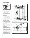
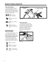
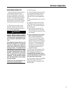
Wheel Drive Control
Use this lever (D, Figure 3-3) to en-
gage and disengage drive to the wheels.
To engage the wheels, first select a
forward or reverse gear with the Gear
Select Lever and squeeze the Operator
Presence Control (A, Figure 3-3). Then,
squeeze the Wheel Drive Control lever
(D) against the handlebar grip. The
ground speed can be varied by increas-
ing or decreasing pressure on the lever.
To avoid sudden acceleration, slowly
squeeze the lever when first engaging
the wheels.
Release the Wheel Drive Control to
disengage the wheels. The wheels will
gradually slow to a stop. NOTE: To stop
the wheels quickly, release the Operator
Presence Control along with the Wheel
Drive Control.
When starting the engine, the Wheel
Drive Control should be disengaged (re-
leased). This helps to ensure that the
wheels will not start turning when the
engine starts.
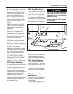
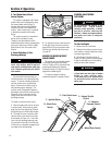
Cutting Height Control Lever
Use this lever (E, Figure 3-4) to adjust
the cutting height from 1 to 4 inches.
Note that actual cutting heights will vary
according to soil conditions.
Turn the lever clockwise to raise the
height or counterclockwise to lower the
height. A decal and pointer (not illus-
trated) on the right side of the mower
deck show the cutting height settings
ranging from A (highest) to G (lowest).
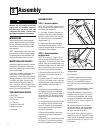
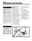
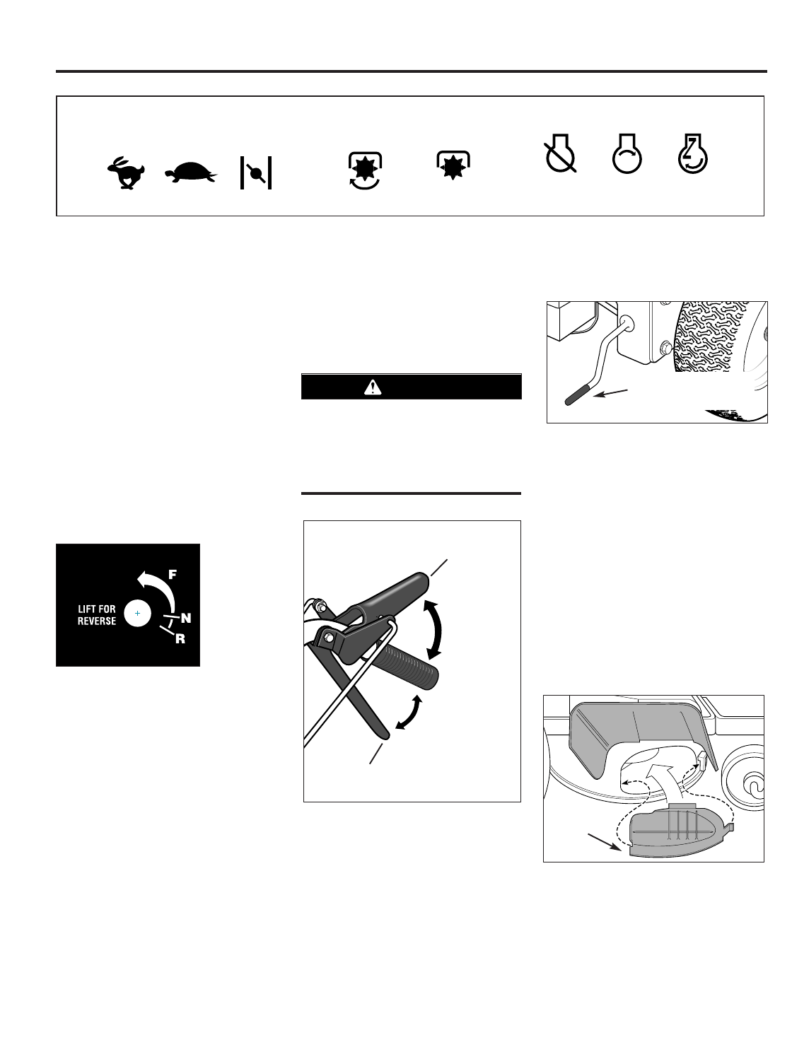
Mulcher Cover
The mulcher cover (F, Figure 3-5) is
pre-installed at the factory. It must be
kept in place when using the unit as a
mulching mower. The mulcher cover is
designed to keep the discharge chute
raised up while you mow. When the
cover is removed for side-discharge
mowing, the discharge chute lowers.
Refer to “4. Select Mulching or Side-
Discharge Mowing” in the Operation
Section for mulcher cover installation
instructions.
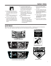
Figure 3-2:
Shift pattern
on console.
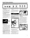
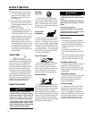
Operating Symbols Various symbols are used on the mower to indicate control settings (your model may not have all of the
symbols). These symbols are shown below with a description of their meaning.
FAST
SLOW
CHOKE
ENGINE
STOP
ENGINE
START
ENGINE
RUN
ENGAGE
DISENGAGE
Do not engage the Wheel Drive Control
without first engaging the Operator
Presence Control. Doing so could
result in wear or damage to the wheel
brake mechanism.
CAUTION
A – OPERATOR
PRESENCE CONTROL
D – WHEEL
DRIVE CONTROL
Disengage
Disengage
Engage
Engage
Figure 3-3
Figure 3-4
E – CUTTING HEIGHT
CONTROL LEVER
F
Figure 3-5