


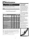
5
Section 2: Assembly
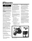
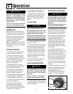
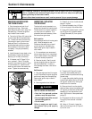
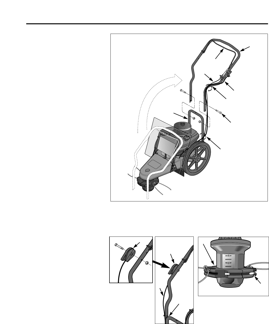
Figure 2-2: Handlebar installation (electric start model shown).
A
C
D
F
E
B
G
F
O
M
M
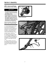
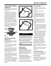
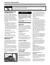
Figure 2-4: Check trimmer head hard-
ware for tightness.
5. Use two cable ties (F, Figure 2-2)
to secure the trimmer head control
cable (C) and the electrical wiring har-
ness (O) to the handlebar at the loca-
tions shown.
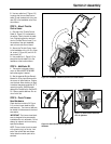
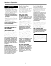
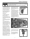
STEP 3: Attach Throttle
Control Lever
1. One end of the Throttle Control
Cable (H, Figure 2-3) is attached to
the engine. Gently unwind the cable
from its shipping position and posi-
tion the Throttle Control Lever (I) on
the outside of the right handlebar,
next to the throttle control decal.
2. Secure the Throttle Control Lever
to the handlebar with a 1/4-20 x 2 hex
hd. screw (J, Figure 2-3) and 1/4-20
hex locknut (K).
3. Use a cable tie (L, Figure 2-3) to
secure the throttle cable (H) to the
handlebar at the location shown.
STEP 4: Add Motor Oil
1. The engine is shipped without
motor oil which MUST BE ADDED
before the engine is started.
2. See the separate Engine Owner’s
Manual for filling instructions and for
the correct oil specifications. Engine
must be level when checking oil level.
In ambient temperatures above 32
0
F,
use a high-quality, SAE 30 weight
detergent oil classified for Service SF -
SJ. Use no special additives. Do not
mix oil with fuel.
STEP 5: Check Trimmer
Head Hardware
Check that the two bolts (M, Figure
2-4) on the trimmer head are tight-
ened securely. The trimmer head can
be rotated to make access to the hard-
ware easier.
IMPORTANT: The trimmer head hard-
ware is designed to be permanently
installed and is not removable. Do not
attempt to replace it with non-factory
specified hardware.
NOTE: The two holes (one is covered
with a plastic plug) on the top, front
end of the mower deck are access
holes that allow certain parts to be
serviced.
Figure 2-3: Attach throttle lever to right-side
handlebar.
I
J
K
L
I
H