


4
Introduction
Carefully follow these assembly steps
to correctly prepare your machine for
use. It is recommended that you read
this Section in its entirety before begin-
ning assembly.
NOTE: If an assembly step applies only
to certain models, those models are
noted at the beginning of that step.
Otherwise, a step applies to all models.
Inspection After Delivery
Inspect your machine immediately after
it has been delivered. Make sure that
neither the carton nor the contents
have been damaged.
If you find or suspect any damage,
contact the carrier (trucking company)
right away. Inform them of the specific
damage and that you wish to file a
claim. To protect your rights, be sure
to put this in writing to the carrier
within 15 days after your machine ar-
rives. Please let us know if you need
assistance with this matter.
IMPORTANT: The engine is shipped
without motor oil in its crankcase.
Motor oil must be added to the engine
before starting.
NOTE: LEFT and RIGHT sides of unit
are as viewed from operator’s position
behind the handlebars.
Tools/Supplies Needed:
• (1) Utility Knife or Scissors
• (2) 1/2" (or adjustable) Wrenches
• (2) 7/16" Wrenches (one with a boxed
end)
• Motor Oil (see Engine Owner’s
Manual for oil specifications and
quantity required)
STEP 1: Unpacking Unit
1. Remove the protective packaging
material (plastic film and cardboard)
from the handlebars and the unit.
2. Remove the handlebars from the
insert and carefully (do not pinch or
kink the attached cables) put them
aside before removing the unit from
the shipping carton.
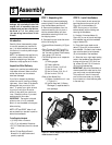
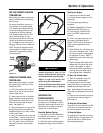
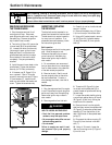
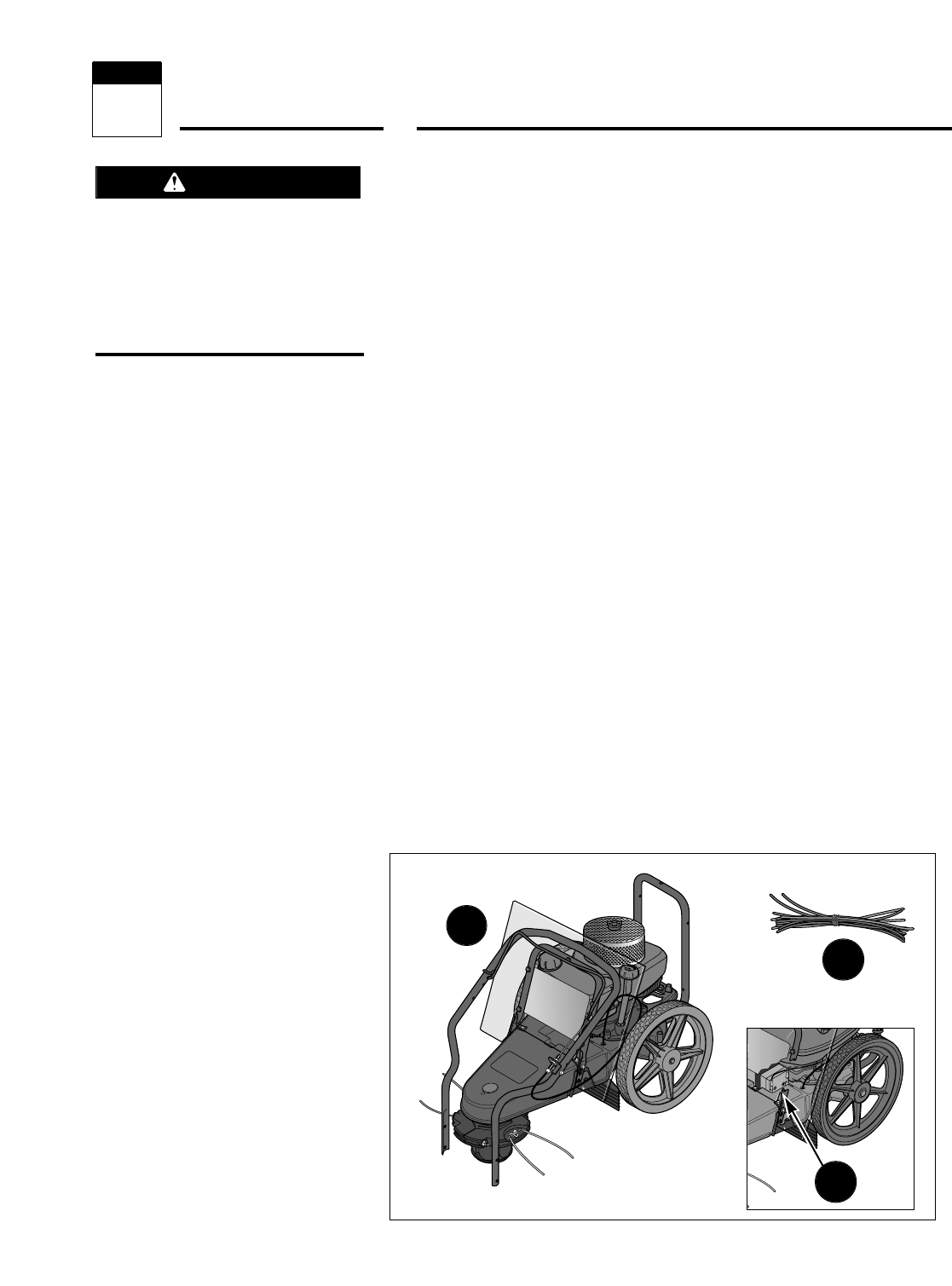
3. Compare the parts inside the carton
with the following list:
• Trimmer/Mower Assembly (A, Figure
2-1)
• Extra Trimmer Line (B, Figure 2-1):
six pieces of heavy-duty gauge .130"
dia. line and six pieces of extra-heavy-
duty gauge .155" dia. line.
• The following items are in a separate
package:
(1) Safety goggles
(3) Plastic cable ties
(1) Hex Hd. Screw, 1/4-20 x 2
(1) Hex Locknut, 1/4-20
(2) Hex Hd. Screw, 5/16-18 x 2
(2) Hex Locknut, 5/16-18
• Electric Start Model Only:
(1) Battery (installed on unit – see
C, Figure 2-1)
(2) Ignition Keys and (1) Battery
Recharger (in separate electric
start package)
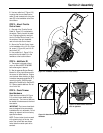
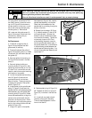
STEP 2: Install Handlebars
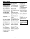
1. Cut the plastic tie and remove the
tape that secures the control bail (G,
Figure 2-2) to the handlebar (A).
NOTE: Do not pinch or kink the at-
tached cable(s) while unfolding and
securing the handlebars.
2. Carefully lift the handlebars (A,
Figure 2-2) to rear of the unit and align
the handlebar legs with the handlebar
support bracket (B).
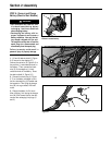
3. Route the trimmer head control
cable (C, Figure 2-2) to the outside of
the handlebar. On electric start models,
also route the electrical wire harness
(O) to the outside of the handlebar.
4. Select the low or high height setting
holes in the handlebar legs and attach
the legs with the two 5/16-18 x 2 hex
hd. screws (D) and 5/16-18 locknuts
(E) from the hardware bag.
IMPORTANT: Adjust the handlebars as
close as possible to waist level so that
your arms are at a comfortable height.
This position will result in less pres-
sure on the mower wear cup, making
the unit easier to roll and reducing wear
to the wear cup.
A
Figure 2-1: Unit as shipped (recoil start model shown). Battery for electric start
model is shown in inset.
B
Assembly
2
Section
To prevent personal injury or property
damage, do not attempt to start the
engine until all assembly steps are
complete and you have read and un-
derstand all of the safety and
the operating instructions in this
Manual.
WARNING
C