


ENGINE MAINTENANCE
IMPORTANT: Refer to the Engine Owner’s
Manual for complete engine maintenance
information.
Engine Oil
• Check the engine oil level each time be-
fore starting the unit and after each 5
hours of operation. With the engine on
level ground, the oil level should be at
the “FULL” mark on the dipstick. Refer to
the engine manual for oil specifications
and complete instructions.
• Change the engine oil according to the
maintenance intervals and instructions in
the engine manual.
TIP: When changing engine oil, fold a
piece of cardboard or aluminum foil into a
shallow “V”, and position it so the oil will
drain through it into the container.
To check the engine oil level:
1. Move the unit to a level surface. Stop
the engine, wait for all parts to stop
moving and disconnect the spark
plug wire from the spark plug.
2. Remove the oil dipstick and wipe the
dipstick with a clean cloth.
3. Screw the oil dipstick back into the oil
fill hole. Remove the dipstick and
check the oil level – it should be up to
the “FULL” mark on the dipstick. If
low, add oil by using the oil dipstick
as a guide. Refer to engine manual
for detailed instructions.
Ignition System
The engine has an electronic ignition sys-
tem which does not use points or a con-
denser. The spark plug is the only item re-
quiring maintenance in this system.
Spark Plug
Annually or every 100 hours of operation,
remove and inspect the spark plug.
Replace the spark plug if the electrode is
pitted or burned or if the porcelain is
cracked. Refer to the engine manual for
correct spark plug specifications and ser-
vicing instructions.
NOTE: Use of an incorrect plug can dam-
age the engine.
Carburetor
The carburetor has been adjusted at the
factory and should not require additional
adjustment. Refer to the engine manual or
contact your dealer for additional carbure-
tor information.
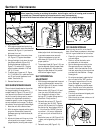
LUBRICATION
At the beginning and end of each season
or after every 25 hours of operation, lubri-
cate the unit as recommended below. The
engine must be stopped and the spark
plug wire disconnected before performing
any lubrication.
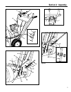
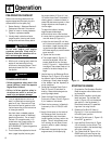
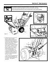
1. Lightly oil both the discharge chute
cap pivot points (A, Figure 5-1).
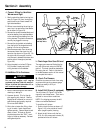
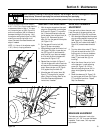
2. Lightly oil the discharge chute control
rod pivot points where the control rod
enters the control panel bearing (B,
Figure 5-3), the support tab (C) and the
support on the left rear of unit housing
(D, Figure 5-4).
3. Remove the left wheel (E, Figure 5-1).
Clean the wheel shaft and apply multi-
purpose grease to the wheel shaft.
Reinstall the wheel.
4. Apply oil to the bearings on the sides of
the auger shaft (F, Figure 5-1).
5. Clean dirt and old grease from the
flange at the bottom of the discharge
chute (G, Figure 5-1). Apply multi-pur-
pose grease to the worm gear (H) and
to the toothed portion of flange and the
flange.
6. Lightly lubricate the handlebar control
levers at pivot points (J, Figure 5-3)
with oil or a non-silicone spray. Do
not get oil or lubricating spray on
levers.
7. Lightly oil the pivot points on the gear
shift control lever (K, Figure 5-3).
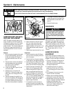
8. Remove the two shear bolts (L, Figure
5-5) from the auger shaft, then lubri-
cate the four auger grease fittings (M,
Figure 5-5) using a grease gun. Rotate
auger three or four times. Reinstall
shear bolts, torque to 11 ft-lbs
(15Nm).
9. Check the auger gear case oil level :
a. Place the unit on a smooth, level
surface. Unscrew the plug
(N, Figure 5-5) from the front of
the gear case.
b. Inspect plug hole. Oil should just
begin to seep out of the hole. Add
SAE 90 gear oil if necessary until
oil just begins to flow out of hole.
Let the excess oil drain out of the
gear case.
c. Reinstall the plug (N).
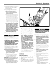
10. Remove bolts (O, Figure 5-4) securing
bottom cover to unit. Remove bottom
cover. Put gear shift lever in highest
speed setting and apply a coating of
multi-purpose grease to the shafts (P
and R, Figure 5-2). Prevent grease
from contacting rubber drive wheel (S)
or drive disk (T). If grease should con-
tact these parts, wipe clean to avoid
slippage and assure proper operation.
Move shift lever between high speed
and reverse settings to spread grease
along shafts. Replace bottom cover.
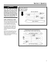
WHEEL DRIVE DISC
ADJUSTMENT
Due to wear, the wheel drive control disc
may begin to slip when wheel drive lever is
engaged. To adjust wheel drive disc:
1. With the engine stopped and the spark
plug wire disconnected, pull the wheel
drive control arm (V, Figure 5-4) down
completely.
2. Put the gear shift lever (AC, Figure 5-
1) in the No. 3 position.
3. Measure and note the distance be-
tween the coiled ends of the spring
(W, Fig, 5-4).
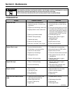
Maintenance
5
Section
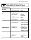
Moving parts on the unit can cause seri-
ous personal injury.
Shut off the engine, let all moving parts
stop completely, disconnect the spark
plug wire and prevent it from touching
the spark plug before performing any
maintenance or service procedures.
WARNING
16