


PRE-OPERATION CHECKLIST
Perform the following checks with the
engine stopped and the spark plug wire
disconnected from the spark plug.
1. Review Section 1: Safety and Section 3:
Features and Controls in this manual.
2. Check for loose or missing hardware.
Tighten or replace as needed.
3. Visually check inside the collector
(auger/impeller) housing and the dis-
charge chute and remove any debris.
4. With the unit on level ground, check the
engine oil level according to the in-
structions in the engine manual. The oil
level should be at the “FULL” mark on
the dipstick.
5. Turn off engine and let it cool for at
least 2 minutes before removing the
gasoline fill cap. Remove the fill cap
and check the level of gasoline in the
fuel tank according to the instructions
in the engine manual.
Use fresh, clean, unleaded gasoline
(refer to engine manual for additional
gasoline information). Do not overfill
fuel tank. Fill to approximately 1-1/2
inches below top of neck to allow for
fuel expansion. DO NOT MIX OIL
WITH GASOLINE! Tighten the gasoline
fill cap securely.
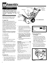
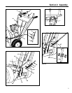
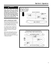
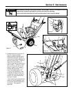
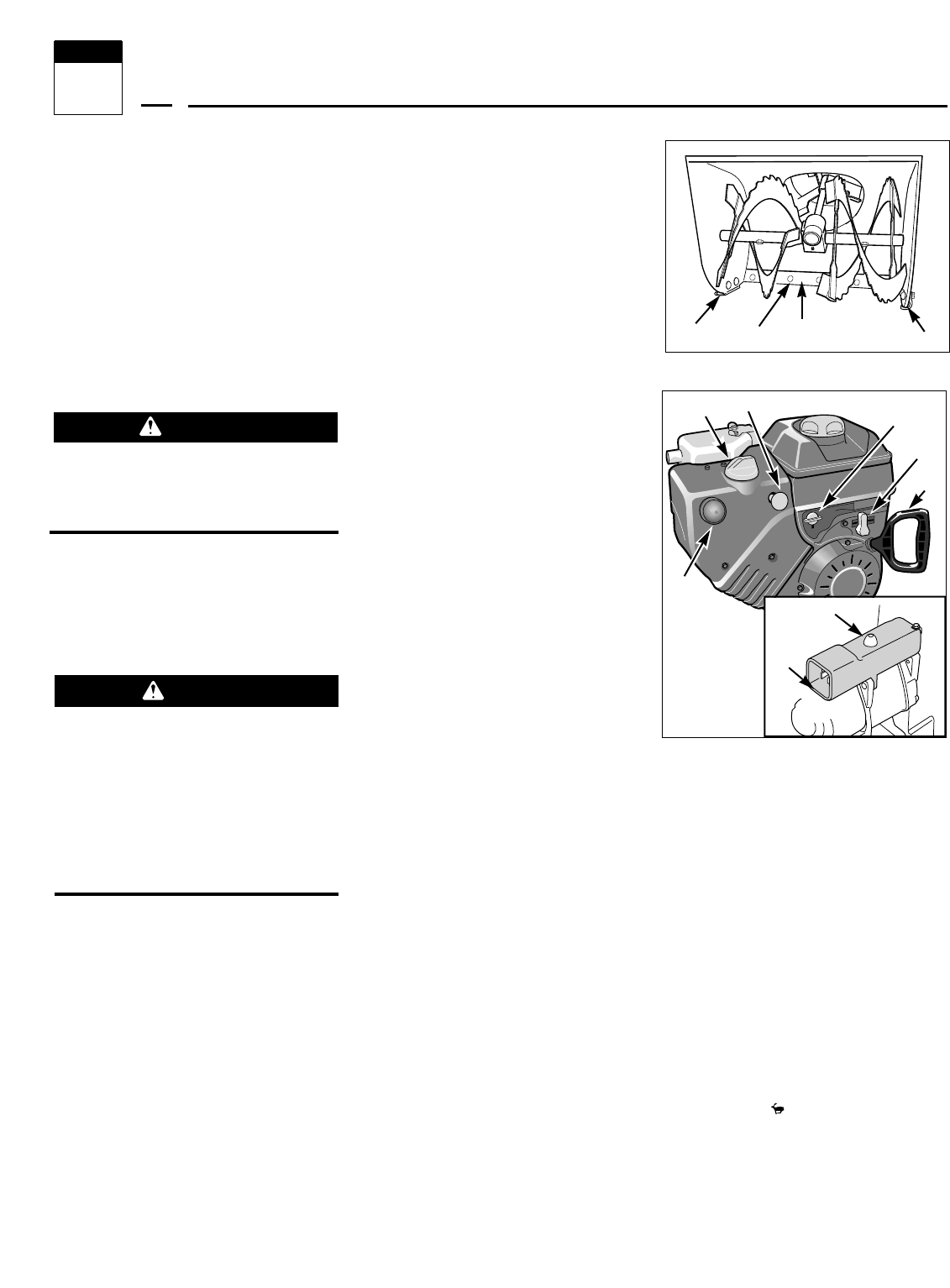
6. The unit should be adjusted so the col-
lector (auger/impeller) housing and
the scraper blade (A, Figure 4-1) are
1/8" above the surface to be cleared. If
clearing gravel or uneven surfaces, in-
crease the clearance so gravel or other
foreign objects are not scooped up
into the auger.
To adjust the collector housing
height/scraper blade height:
a. Move the unit onto a level surface.
b. Loosen the four screws securing the
two skid shoes (B, Figure 4-1).
c. Adjust the skid shoes (B) until they
are in the correct position to support
the collector (auger/impeller) hous-
ing and the scraper blade (adjust
skid shoes equally to prevent uneven
snow removal).
d. Tighten the four screws.
e. The scraper blade (A, Figure 4-1)
can also be adjusted. Adjust the
scraper blade at the four carriage
bolts (C, Figure 4-1). Adjust the bot-
tom edge of the scraper blade so it is
parallel to the bottom edge of the
auger.
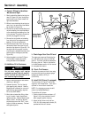
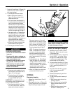
7. Use the lever on the Discharge Chute
Deflector Cap (D, Figure 4-3) to adjust
the deflector cap to the desired angle
of discharge. Usually keep the angle
of the deflector cap low, especially in
windy conditions.
8. Rotate the Discharge Chute Control
Rod (E, Figure 4-3) and check for
binding. Leave the discharge chute
pointing straight ahead.
9. Check the Auger Drive and Wheel
Drive control levers (F and G, Figure 4-
3) for freedom of movement.
10. Check the tire pressure. Inflate both
tires evenly to 8 to 12 PSI (55 to 82
Kpa).
11. Apply silicone spray on the inside of
the discharge chute, the chute dis-
charge deflector cap, the collector
(auger/impeller) housing, and on the
augers. This will help prevent snow
from sticking (do not allow silicone
spray on rubber or plastic: damage
can result).
12. Reconnect the spark plug wire (see
engine manual) to the spark plug.
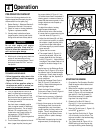
STARTING THE ENGINE
1. Complete the Pre-Operation Checklist.
Read the engine manual before start-
ing the engine.
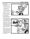
2. Move the unit outside to a well-venti-
lated, level area. Put the Gear Shift
Lever (H, Figure 4-3) into the desired
gear position. Use the slowest (1)
forward and reverse (R1) speed set-
ting when first using the unit.
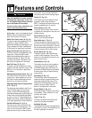
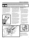
3. Rotate the Fuel Shut-Off Valve (J,
Figure 4-2) 1/4 turn counterclockwise
to the ON (open) position.
4. Move the Throttle Lever (L, Figure 4-2)
to the FAST position.
5. Insert the Stop Switch Key (K, Figure
4-2) all the way into the switch. (The
key was included in the hardware bag
with other loose parts.)
6. Turn Choke Knob (M, Figure 4-2) to
CHOKE setting (a warm engine may
not require choking when restarting).
CAUTION
Do not start engine until engine
crankcase has been filled with oil.
Failure to follow this instruction will re-
sult in serious engine damage.
Operation
4
Section
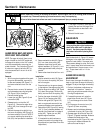
GASOLINE IS HIGHLY FLAMMABLE AND
ITS VAPORS ARE EXPLOSIVE.
• Follow the gasoline safety rules in this
manual (Section 1) and in the separate
Engine Owner’s Manual.
• Failure to follow gasoline safety in-
structions can result in serious per-
sonal injury and property damage.
DANGER
Figure 4-2
N
O
K
M
J
L
P
R
Figure 4-1
A
B
B
C
12