


Section 2: Assembly
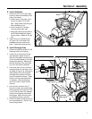
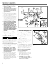
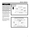
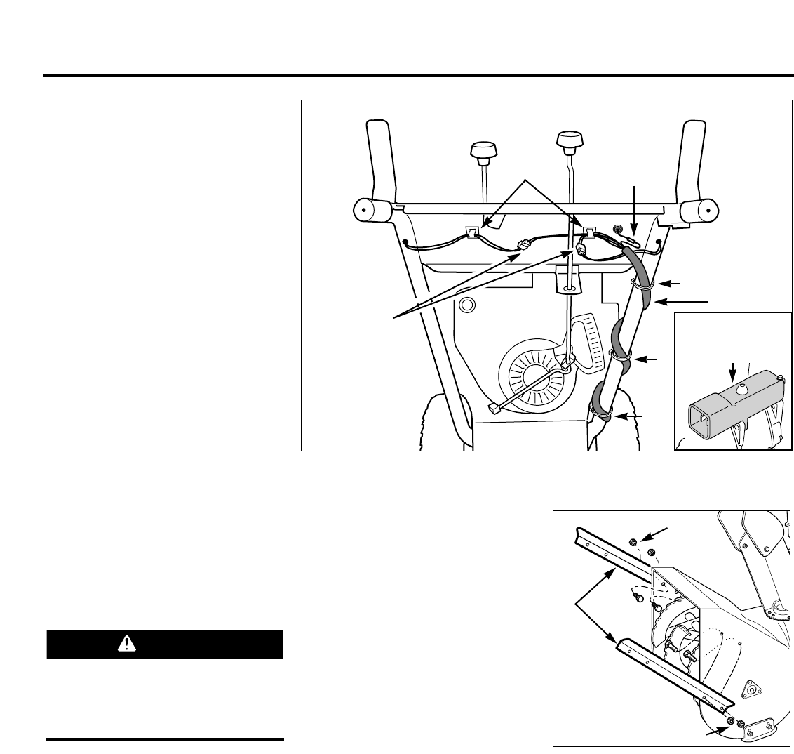
J. Connect Wiring for Handlebar
Warmers and Light
1. Gently unwind the electrical wiring har-
ness (A, Figure 2-9) from its shipping
position and route it back toward the
right-side handlebar.
2. Without over-stretching the wiring har-
ness, loop it up and around the handle-
bar as shown in Figure 2-9.
3. Connect the double-stranded black and
red wires leading from each handlebar
to the matching wires leading from the
wiring harness. The plastic connectors
can only be plugged in one way.
4. Connect the single black wire leading
from the light to the single black wire
leading from the wiring harness.
5. Remove excess slack from the wiring
harness and insert the wires into the
two wire clips shown in Figure 2-9. On
the right-side of the engine, tuck the
wire harness in between the starter box
and the side of the engine (see inset,
Figure 2-9).
6. Using the plastic wire ties (B, Figure
2-9) provided, loosely secure the
wiring harness to the handlebar.
K. Add Motor Oil to Crankcase
1. Be sure that the engine is level before
checking or adding oil.
2. Unscrew dipstick. Fill oil at the dip-
stick opening with fresh oil. See the
Engine Owner’s Manual for correct oil
specifications and quantity required.
Do not use SAE 10W40.
3. Wait a few minutes after filling, allow-
ing oil to settle. Insert dipstick and
tighten securely. Remove dipstick and
check oil level. Oil level on dipstick
should always be at the “FULL” mark.
Adjust oil level as necessary. Reinsert
and tighten dipstick.
L. Check Auger Gear Case Oil Level
The auger gear case was filled at the fac-
tory with the correct amount of SAE 90
gear oil. This level should be checked be-
fore using the unit. Refer to Lubrication
in the Maintenance section of this manual
for complete information.
M. Check Tire Pressure
Check the air pressure in both tires using
an automotive-type tire pressure gauge.
Inflate tires evenly to 8-12 psi
(55-82 kPa).
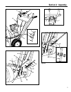
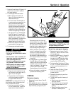
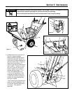
N. Install Drift Slicers (if equipped)
The drift slicers (C, Figure 2-10) are de-
signed for use in deep snow. Their use is
optional for normal snow conditions.
NOTE: For shipping purposes, the drift
slicers are installed backward.
To install the drift slicers:
1. Position the drift slicers as shown, (C,
Figure 2-10) to the outside of the col-
lector (auger/impeller) housing.
2. Attach the drift slicers with the four
5/16–18 x 3/4 screws and locknuts (D)
provided with the drift slicers.
Connect Double
Stranded (Black
and Red) Wires
Connect
Single (Black)
Wires
Wire Clips
A
B
CAUTION
Do not start engine until engine
crankcase has been filled with motor oil.
Failure to follow this instruction will re-
sult in serious engine damage.
C
D
D
Figure 2-10
Figure 2-9
B
B
10
Tuck Wire Harness
between Starter Box
and Engine