


Section
3
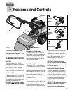
Features and Controls
This section describes the various
features and controls on the unit. Refer
to the next section, “Operation,” for an
explanation of the use of these controls.
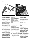
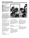
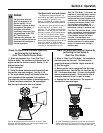
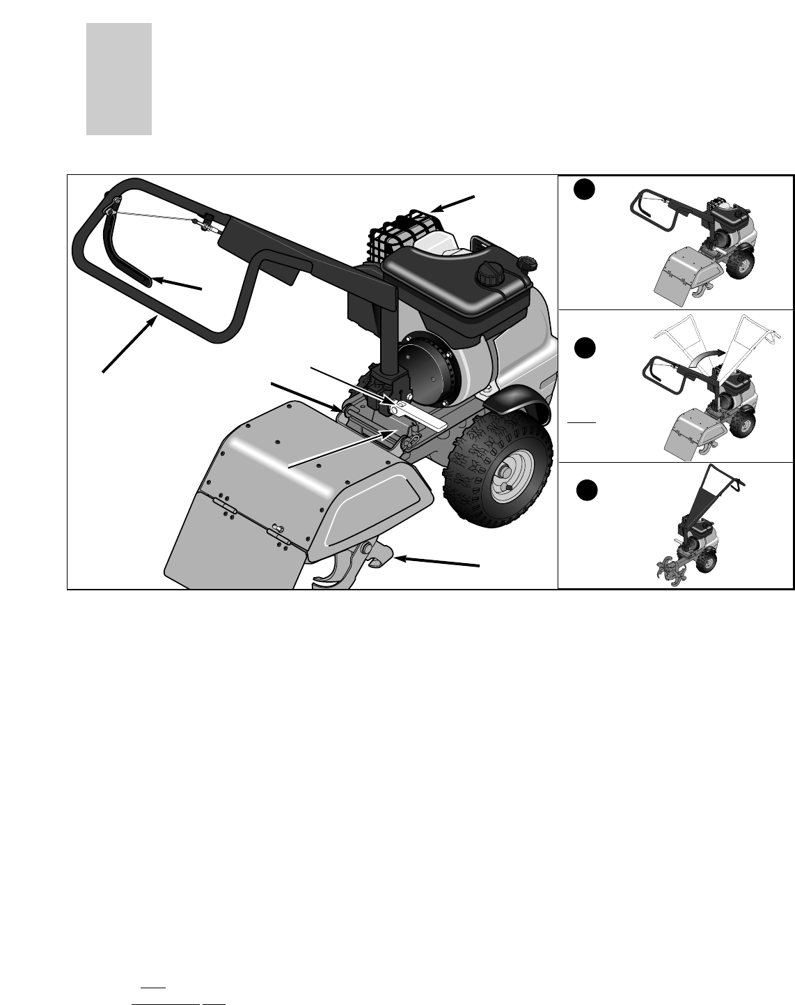
TILLER FEATURES/CONTROLS
Drive Bail
Holding the Drive Bail (A, Fig. 3-1)
closed against the handlebar engages the
tines and wheels (when handlebar is in
the rear tine tiller mode) or engages
power to just the tines (when handlebar is
turned to front tine tiller/cultivator mode).
Swivel Handlebar
The handlebar (B, Fig. 3-1) swivels 180
o
to convert the equipment into either a rear
tine tiller or a front tine tiller/cultivator.
The handlebar also offers infinite height
adjustments for operator comfort.
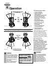
IMPORTANT: Only swivel the handlebar
180
o
on the muffler cage side of the equip-
ment, or damage to the unit can occur!
Handlebar Locking Lever
Lift up the lever (C, Fig. 3-1) to unlock
the handlebar. This allows the handlebar
height to be raised or lowered, and the
handlebar to be swiveled 180
o
. See Inset
Figures above for rear tine tiller and front
tine tiller/cultivator modes.
Hood Release Pin
This pin (D, Fig. 3-1) locks the hood to
the tiller chassis. When the pin is taken out
the hood can be removed and then the
handlebar swiveled around and positioned
over the engine for cultivating. NOTE: The
hood must always be in place and locked
with the hood release pin when the
machine is used for rear tine tilling or else
the engine will not run.
Tines
Four tine sets (E, Fig. 3-1) (each set has
four tines) rotate at high speed and
do the tilling and cultivating in the soil.
When you are rear tine tilling and stand-
ing in the operator’s position behind the
hood, the tines rotate counterclockwise
(CRT) in a direction opposite from forward
travel. When you are front tine tilling or
cultivating (hood is removed; handlebar is
swung 180
o
over the engine), the tines
rotate clockwise in the direction of
forward travel.
IMPORTANT: In rear tine tiller mode,
both the tines and wheels are powered.
In front tine tiller/cultivator mode, only
the tines are powered.
Operational Interlock System
Located at the base of the handlebar (F,
Fig. 3-1). This safety switch shuts the
engine off or prevents it from starting if
the operator attempts rear tine tilling with
the tine hood off, or attempts front tine
tilling/cultivating with the handlebar in
any position other than pointing back
over the engine.
IMPORTANT: Do not attempt to operate
machine in front tine tiller/cultivator
mode with the tine hood installed as
damage to the tine hood could occur.
Fig. 3-1
A
B
C
D
E
F
Rear Tine
Tiller Mode
(tine hood
must be on)
Swivel
Handlebar
on this side
ONLY
Front Tine
Tiller/
Cultivator Mode
(tine hood must
be removed)
1
2
3
9
MUFFLER
CAGE