


10
Section 3: Features and Controls
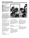
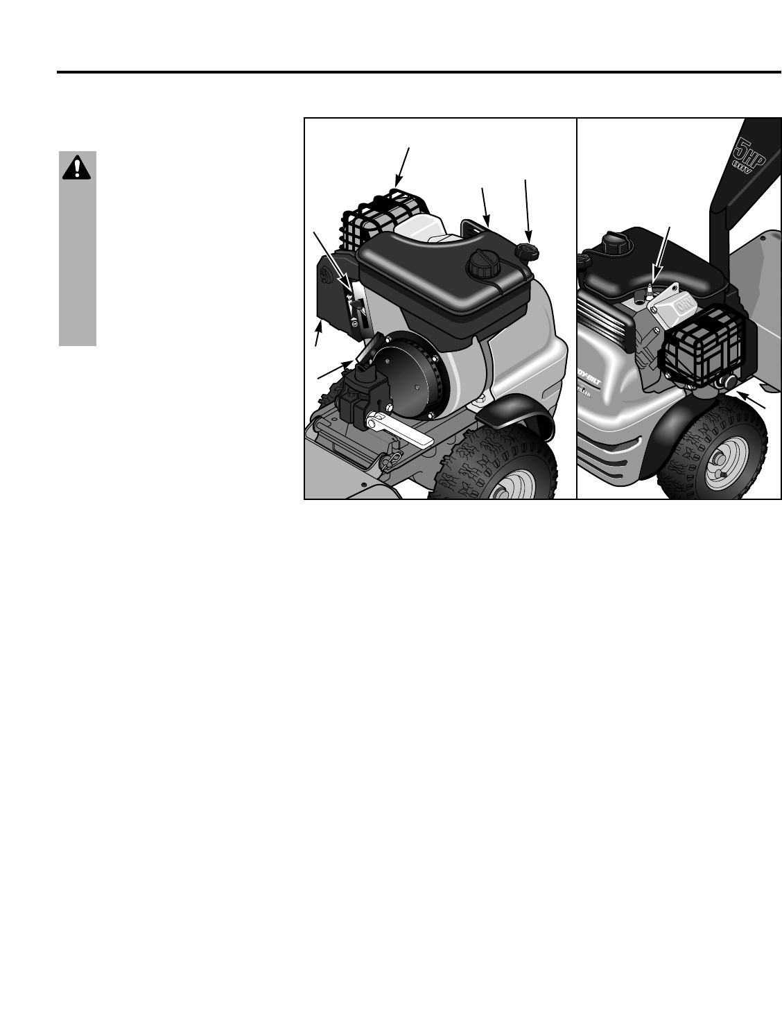
ENGINE FEATURES/CONTROLS
The following are descriptions of the
features and controls on your engine.
Additional engine information is
provided in Section 4 “Operation” in this
manual and in the engine manufacturer’s
Operator’s Manual which is included in
your literature package. Be sure to read
the Engine Operator’s Manual carefully
and save it for future reference.
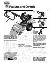
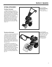
Engine Throttle Lever
The throttle lever (G, Fig. 3-2) is used to
adjust engine speed as well as start and
stop the engine.
Move the throttle lever all the way up
from the STOP position to the START/RUN
position before pulling out the recoil
starter. There is an IDLE position between
the STOP and START/RUN positions.
Move the throttle lever down to the STOP
position to turn the engine off.
Fuel Primer Bulb
This bulb (H, Fig. 3-2) pumps a small
amount of gasoline into the carburetor to
aid in starting the engine. Refer to the
following section, “Operation,” for
specific primer bulb operating
information under various starting
conditions.
Recoil Starter
The recoil starter (I, Fig. 3-2) is used to
manually start the engine.
Oil Fill Tube and Dipstick
Turn and lift up to remove the oil
dipstick (J, Fig. 3-2) from the top of the
engine. Always keep the oil level between
the “ADD” and “FULL” marks at the end of
the dipstick. Refer to your Engine
Operator’s Manual for specific motor oil
recommendations.
Fuel Tank
The fuel tank and cap are on top of the
engine (K, Fig. 3-2).
Spark Plug
The spark plug wire (L, Fig. 3-2) must
be securely attached to the spark plug in
order for the engine to start and run
properly. Always disconnect the spark
plug wire and move it away from the plug
before performing any repairs or
maintenance.
Air Cleaner
Your engine has a dual element air
cleaner system for maximum filtration
efficiency (see M, Fig. 3-2). Never run
the engine without the complete air
cleaner installed. Service the air filter
system regularly as specified in your
Engine Operator’s Manual.
Muffler
The engine muffler (N, Fig. 3-2) has a
steel cage surrounding it to keep objects
away from its hot surface. Do not touch
the engine muffler while the engine is
running or cooling down.
Fig. 3-2: Engine features and controls.
J
K
M
N
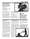
WARNING
Before operating your machine,
be sure you read and understand
all safety, controls, and opera-
ting instructions in this Owner’s
Manual and on the decals on
your machine.
Failure to follow these instruc-
tions can result in serious injury
or property damage.
L
I
H
G