


7
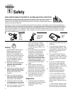
WARNING
TO PREVENT PERSONAL INJURY
OR PROPERTY DAMAGE, DO
NOT START THE ENGINE UNTIL
ALL ASSEMBLY STEPS ARE
COMPLETE AND YOU HAVE READ
AND UNDERSTAND THE SAFETY
AND OPERATING INSTRUCTIONS
IN THIS MANUAL.
Inspect unit
Inspect the unit and carton for damage
immediately after delivery. Contact the
carrier (trucking company) if you find or
suspect damage. Inform them of the
damage and request instructions for filing
a claim. To protect your rights, put your
claim in writing and mail a copy to the
carrier within 15 days after the unit has
been delivered. Contact the factory if you
need assistance in this matter.
Tools/Materials Needed for
Assembly
(One) 1/2" wrench*
(Two) 9/16" wrenches*
(One) Automotive-type air pressure gauge
(One) Clean oil funnel
(One) Quart clean, high-quality engine oil.
Refer to the Engine Owner Manual
for engine oil specifications and
quantity required. Do not overfill.
* Adjustable wrenches may be
substituted.
IMPORTANT: Motor oil must be added to
the engine before starting. Follow the
instructions in this “Assembly” section
and in the Engine Owner’s Manual.
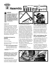
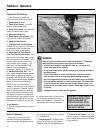
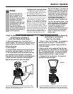
Unpacking Instructions
1. After opening the carton, remove card-
board support materials and packaging
material around handlebar and engine.
2. Lift up the carton to remove it.
3. Carefully put aside the upper section
of the handlebar (it is connected to the
machine by a control cable) and the hard-
ware bag. See Fig. 2-1. Do not kink the
control cable connected to the uper handle-
bar section. Also cut the plastic tie on the
handlebar to free the drive bail (Fig. 2-1).
4. The assembly is easiest by leaving the
tiller on the wood shipping pallet until the
handlebar has been completely assembled.
If the unit must be moved off the pallet
and rolled to another location for assem-
bly, see “Freewheel” message on Pg. 8.
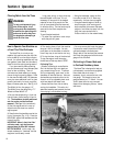
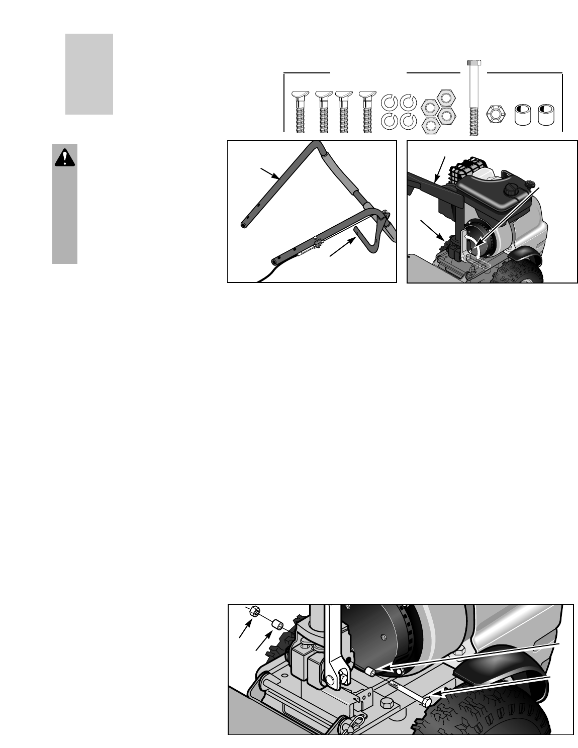
5. Open the hardware bag and group the
hardware. Check the contents against the
following list and Fig. 2-1A above (hard-
ware shown at a reduced size):
• four 5/16"-18 x 1-1/2" curved head screws
• four 5/16" lockwashers
• four 5/16"-18 hex nuts
• one 3/8"-16 x 3-1/4" screw
• one 3/8"-16 locknut
• two steel bushings (for handlebar)
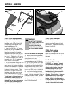
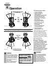
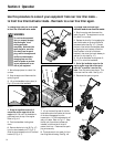
STEP 1: Adjust Handlebar Height
1. Move the handlebar locking lever up
(A, Fig. 2-2), then tilt the lower handlebar
section upward to align the holes in the
base and the lower handlebar section (B).
2. Hold the lower handlebar section in
this position with the holes in the base
aligned. Move the handlebar locking
lever down to “freeze” the hole alignment.
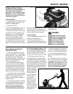
STEP 2: Install Hardware in Base
and Lower Handlebar Section
1. Insert one bushing (C, Fig. 2-3) on the
end of the 3-1/4" long screw (D), and
slide the screw through the base of the
lower handlebar section. Put the other
bushing (C) on the screw on the other
side, sliding it on all the way.
2. Use 9/16" wrenches to install the 3/8"
locknut (E) on the screw (D). Tighten hard-
ware securely. NOTE: Do not tighten the
other long screw next to this hardware – it
is factory tightened. See Fig. 2-3.
Section
2
Assembly
Fig. 2-1
Fig. 2-2
Upper
Handlebar
Section
Cut plastic tie to
free the drive bail
Fig. 2-3: Install hardware to secure lower handlebar section to the base.
C
C
D
B
Hardware Shipped
Fig. 2-1A
A
Lower Handlebar
Section
E