


22
Maintenance of the
Operational Interlock System
The Operational Interlock System is an
electrical safety system that prevents the
engine from starting (or shuts the engine
off) if either of two unsafe operating
conditions were to occur: 1) while in use
as a rear tine tiller with the handlebar
extending over the tine hood, the interlock
will shut the engine off if the tine hood
were not securely locked in place; 2)
while in use as a front tine tiller/cultivator
with the hood removed and the
handlebars positioned over the engine,
the interlock will shut the engine off if the
handlebar is swiveled more than 90
0
toward the exposed tines.
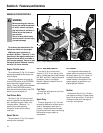
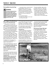
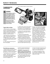
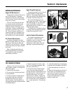
Keep the interlock switch area (M,
Fig.5-5) clean and free of all debris.
Inspect this location every time the
equipment is used and clean if dirty.
Also check the two electrical
connections (N and O, Fig. 5-6) on the
engine. The connectors must be securely
attached.
Section 5: Maintenance
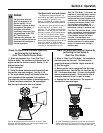
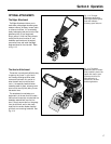
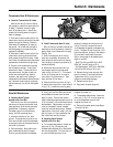
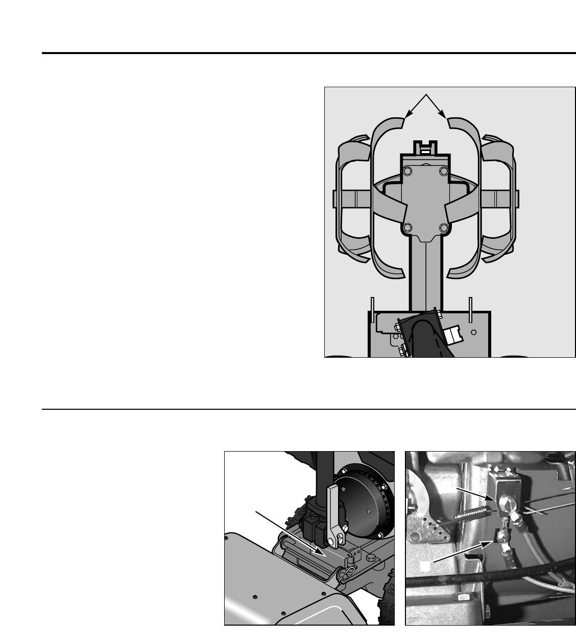
Tine Maintenance
Tine Sets Should Be Inspected
Regularly and Replaced When Worn
Inspect the tines every 25 hours of
operation (or at least a couple of times a
year) for wear and general condition. If
any tines are broken, or if you notice that
tilling and cultivating do not mix the soil
as thoroughly as when the tines were
new, it’s time to inspect and perhaps
replace the tine sets. Refer to your parts
catalog for correct part number
information. NOTE: The tine sets with the
thicker tines must be positioned closest
to the transmission. The hardware
securing the tine sets must be tightened
securely (8 ft-lbs.).
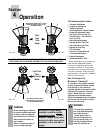
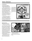
The tine sets must be reinstalled as
shipped originally from the factory. The
tines are designed to rotate backward,
with their curved cutting edges entering
the soil first. If mounted incorrectly, the
tines may tend to run along on top of the
ground rather than digging in the soil.
This could unexpected-
ly cause the machine to
jump backward. Also–
the tines must all point
inward and the two tine
sets with the thicker
tines must be mounted
inboard, as seen in Fig.
5-4.
Fig. 5-4: All of the tines point inward. The tines are thicker on the two
inner sets. Tines must be mounted so each tine’s cutting edge enters
the soil first.
Fig. 5-5: Location of interlock switch.
Fig. 5-6: Engine shutoff locations.
M
N
O
THE TWO INNER TINE
SETS HAVE THICKER TINES
ALL TINES MUST
FACE INWARD AND
TINE CUTTING EDGES
MUST ENTER
SOIL FIRST