


6F3B0253
Basic Hardware and Function 249
7. Instructions
< Monitor mode (Mode 1) >
When the instruction input comes ON with the operand B+1 is 1, the Monitor mode (mode 1) is
selected.
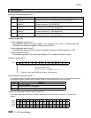
In this mode, the T1-16S sends the following Read commands to the Inverters starting from #0
through the Inverter number specified by the operand B, and repeats.
#0 Operating frequency monitor (FD00)
#0 Output terminal status monitor (FE07)
#1 Operating frequency monitor (FD00)
#1 Output terminal status monitor (FE07)
:
#n Operating frequency monitor (FD00)
#n Output terminal status monitor (FE07)
The maximum Inverter number #n is specified by the operand B.
The scan execution status and the Inverter communication status are stored in the operand
B+2 to B+7.
The monitor data table is specified by the operand A and A+1.
When the instruction input is reset to OFF, the operation is stopped after receiving the
response from the Inverter currently communicating.
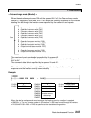
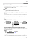
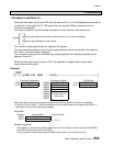
Example
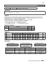
Data table designation Parameter & status RS-485 port
D1000 3 RW200 19 D1010 H0030 (fixed)
D1001 100 RW201 1 (mode 1) D1011 0 (fixed)
RW202 Execution status
RW203 Comm error code
RW204
RW205 Inverter comms
RW206 status map
RW207
When the data for each operand are set as above, the following operation condition is specified.
• RW200=19 ⇒ The max Inverter number is 19. Therefore T1-16S scans from #0 through #19 Inverters.
• D1000=3 & D1001=100 ⇒ RW100 is specified as the data table starting address.
Scan