


6F3B0253
Basic Hardware and Function
101
6. Programming Information
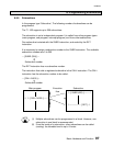
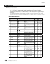
Sampling trace function
The sampling trace function collects the status of specified devices or register at every
specified sampling timing. The collected data can be displayed on the programmer
(T-PDS) screen in the format of timing chart (for devices) or trend graph (for register).
The minimum sampling timing is the T1-16S’s scan cycle.
This function is useful for program debugging and troubleshooting.
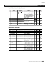
T1-16S
Sampling target Devices (up to 8) and
Registers (up to 3)
Sampling capacity 256 times
The collected data is stored in the T1-16S internal buffer.
The buffer works as a ring buffer, and latest collected data can be displayed.
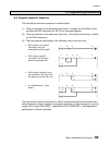
The sampling start/stop condition (arm condition) and the collection timing (trigger
condition) can be specified by status changing of devices.
For detailed key operations for arm/trigger conditions setting on the T-PDS, refer to
the manual for T-PDS.
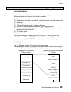
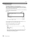
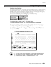
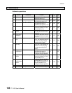
T-PDS screen example of device timing chart
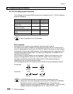
(1) On the T-PDS, select ‘3 registers + 8 devices’ as the sampling type.
(2) As the arm and trigger conditions, register values cannot be used.
(3) The After times setting is not effective for the T1-16S.
NOTE