


6F3B0253
220 T1-16S User’s Manual
7. Instructions
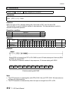
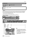
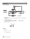
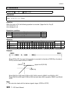
Control block diagram
1
T
I
⋅
s
Differential limit
Derivative
Proportional
Integral
Differential
∆
MV
n
(
η
= 0.1)
MVS: Velocity
→
Position
MV
n
= MV
n-1
±
∆
MV
n
H/L: Upper / lower limit
DMV: Differential limit
MVC
n
MV
n
Manual
mode
Cascade
mode
Auto
mode
Digtal filter
MV
MMV
PVC
∆
D
n
∆
P
n
∆
I
n
e
n
PV
n
SV
n
CSV
ASV
-
+
-
+
+
1
T
D
⋅
s
1+
η⋅
T
D
⋅
s
1
1+T
⋅
s
Gap K
P
MVS H/L DMV
DSV
DMMV
Integral
control
Integral action control:
When MV is limited (H/L, DMV) and the integral value has same sign as limit over, integral action
is stopped.
Velocity → Position conversion:
In Direct mode, MV increases when PV is increased. → MV
n
= MV
n-1
- ∆Mv
n
In Reverse mode, MV decreases when PV is increased. → MV
n
= MV
n-1
+ ∆MV
n
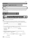
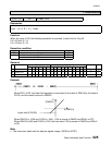
Gap (dead-band) operation:
Error e
SV - PV
GP (%) GP (%)
Algorithm
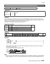
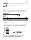
Digital filter:
PV FT PVC FT PV
nn
=− ⋅ + ⋅
−
()1
1
Here,
0 000 0 999..≤≤FT