12
SYSTEMS INDICATOR MONITOR
LCD
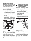
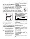
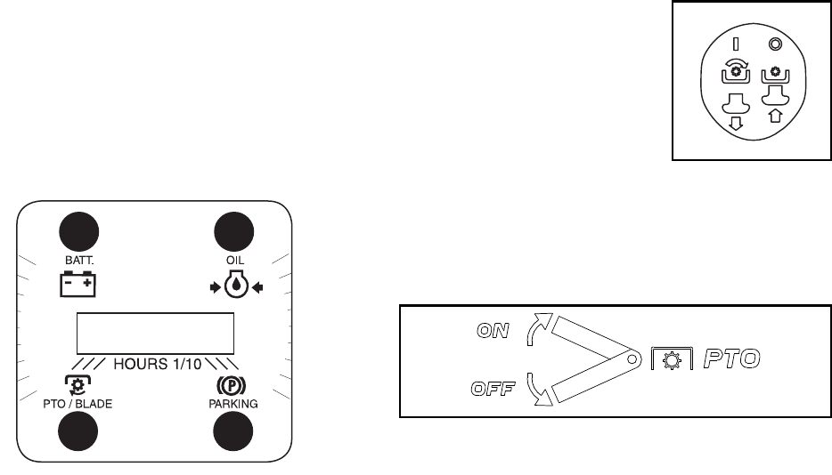
Located in the center of the tractor’s console, the
systems indicator monitor records, and displays on its
LCD, hours of tractor operation whenever the ignition
key is rotated out of the STOP position.
The indicator Monitor will also remind the operator of
maintenacne intervals for changing the engine oil. The
LCD will alternately flash the recorded hours, “CHG”
and “OIL” for five minutes, after every 50 hours of
recorded operation elapse. The maintenance interval
lasts for two hours (from 50-52, 100-102, 150-152,
etc.). The LCD will also flash as described above for
five minutes every time the tractor’s engine has been
started during this maintenance interval. Before the
interval expires, change the crankcase oil level as
instructed in this Operator’s Manual.
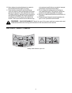
Figure 7
If the Brake light or PTO light illuminates when
attempting to start the unit, proceed as follows:
Brake — Engage the parking brake.
PTO — Move the PTO lever into the disengaged
(Blade Stop) position.
It is normal for the Oil light and the Battery light to
illuminate while the engine is cranking, but if either
illuminates while the engine is running, proceed as
follows:
Oil— Stop the tractor immediately and check the
crankcase oil level as instructed in the
Engine Owner’s Manual included with
your unit. Add oil as required.
Battery— If this light illuminate’s while the engine is
running, it indicates that the battery is in
need of a charge OR that the engine’s
charging system is not generating
sufficient amperage. Refer to the
MAINTENANCE section of this manual
for the proper battery charging procedure
or have the engine’s charging system
checked by a authorized dealer.
On units so equipped, the ammeter measures the
electrical output of the engine’s charging system. Under
normal operating conditions, with the engine at full
throttle, the ammeter’s needle should measure a
positive charge.
The hour meter, on units so equipped, operates
whenever the engine is running and records the actual
hours of tractor operation.
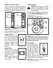
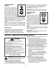
ELECTRIC PTO (POWER
TAKE-OFF) KNOB
To engage the power to the
cutting deck or other (separately
available) attachments on
models so equipped with an
electric PTO, pull outward on the
PTO knob. Push the PTO knob
inward to disengage the power to the cutting deck.
NOTE: The PTO knob must be in the disengaged
(Blade Stop) position when starting the engine.
PTO (POWER TAKE-OFF) LEVER
On models equipped with a manual PTO, the PTO lever
is located on the left side of the dashboard next to the
steering wheel. Move the PTO lever forward to engage
the power to the cutting deck or other (separately
available) attachments; move the PTO lever rearward
to disengage the power.
NOTE: The PTO lever must be in the disengaged
(Blade Stop) position when starting the engine.
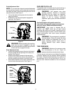
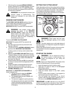
SEAT ADJUSTMENT LEVER
To adjust the seat forward or backward on units
equipped with a quick-adjust seat, slide the seat
adjustment lever to the left and reposition the seat to
the desired position. Once a comfortable position is
found, release the seat adjustment lever to lock the
seat in place. Refer to SEAT ADJUSTMENTS in the
MAKING ADJUSTMENTS section of this manual for
more detailed instructions.
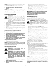
DECK LIFT LEVER
Found on your tractor’s right fender, the deck lift lever is
used to change the height of the cutting deck. To use,
move the lever to the left, then place in the notch best
suited for your application.
CUP HOLDER
The tractor’s cup holder is located on the fender to the
left of the seat, just to the rear of the parking brake
lever.
{Ó°äÊ


