


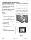
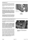
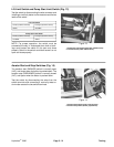

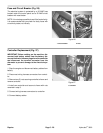

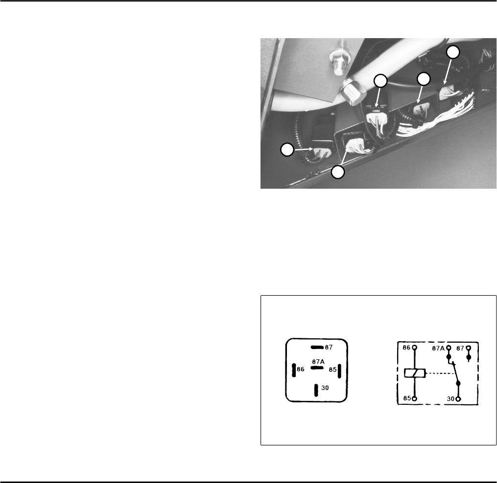
Relays (Fig. 19, 20)
To test a relay, disconnect the relay wire connector and
install a continuity tester between the relay terminals
(terminals 30 and 87). The relay should make and break
continuity at terminals 30 and 87 as 12 V.D.C. is con-
nected and disconnected to terminal 85 with terminal 86
connected to ground.
Resistance specifications:
Terminals 85 and 86 = 80 to 90 Ohms
Terminals 30 and 87a (normally closed) = continuity
Terminals 30 and 87 (normally open) = continuity when 12V
DC is applied to terminals 85 and 86
Battery
Use a hydrometer to test the battery. Charge the battery
if necessary (see Battery Service).
Electrolyte Specific Gravity
Fully charged: 1.250 - 1.280
Discharged: less than 1.240
1
2
3
5
4
Figure 19
RELAY (WIRE COLORS)
1. Valve clutch (brown, gray, red, pink)
2. Lift up –– transport (green, black, red, green, black)
3. Lift down –– aerate (brown, white, blue, red, black)
4. Pump clutch (blue, yellow, purple, red)
5. Start (yellow, red/blue, brown, red)
Figure 20
Testing Page 5 - 24
Rev. B
HydroJect 3000