Two Stage Snowthrower Drive Systems Manual 3 - 13
Traction Drive Systems
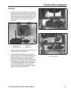
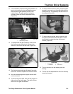
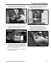
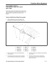
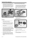
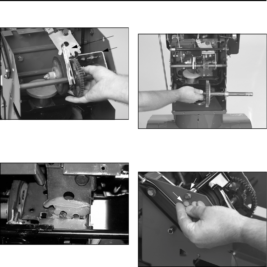
17. Install the friction wheel and sliding bracket. The
friction wheel should be on your left (Figure 109).
Figure 109
2773-081
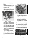
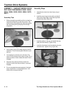
The gear quadrant must be free to pivot. The first
tooth on the quadrant should go into the hole in
the right side as shown in Figure 110.
Figure 110
MVC-716
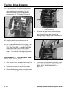
Secure with 2 shoulder bolts. One through each
side of the frame into the shaft. Assure the shaft is
free to pivot. If not, loosen the shoulder bolts and
relieve the binding (Figure 109).
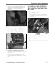
18. Clean the axle so dirt or rust does not damage the
bearing during installation.
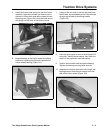
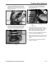
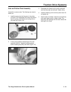
19. Install a thrust washer and bearing on each end of
the axle. Locate the holes and secure the axle
bearings to the frame (Figure 111).
Figure 111
773-074
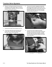
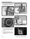
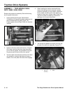
20. Slip the spacer on the end of the traction
engagement assembly. Slide the assembly into
the holes in the frame and secure the left end of
the shaft with a retaining ring (Figure 112).
Figure 112
2773-079
1
2
1
.
G
ear qua
d
ran
t2
.
Slidi
ng
b
rac
k
e
t
1
2
1
.
S
pacer
2
.
R
e
t
a
i
n
i
ng r
i
ng


