Traction Drive Systems
3 - 8 Two Stage Snowthrower Drive Systems Manual
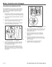
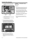
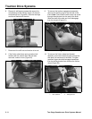
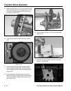
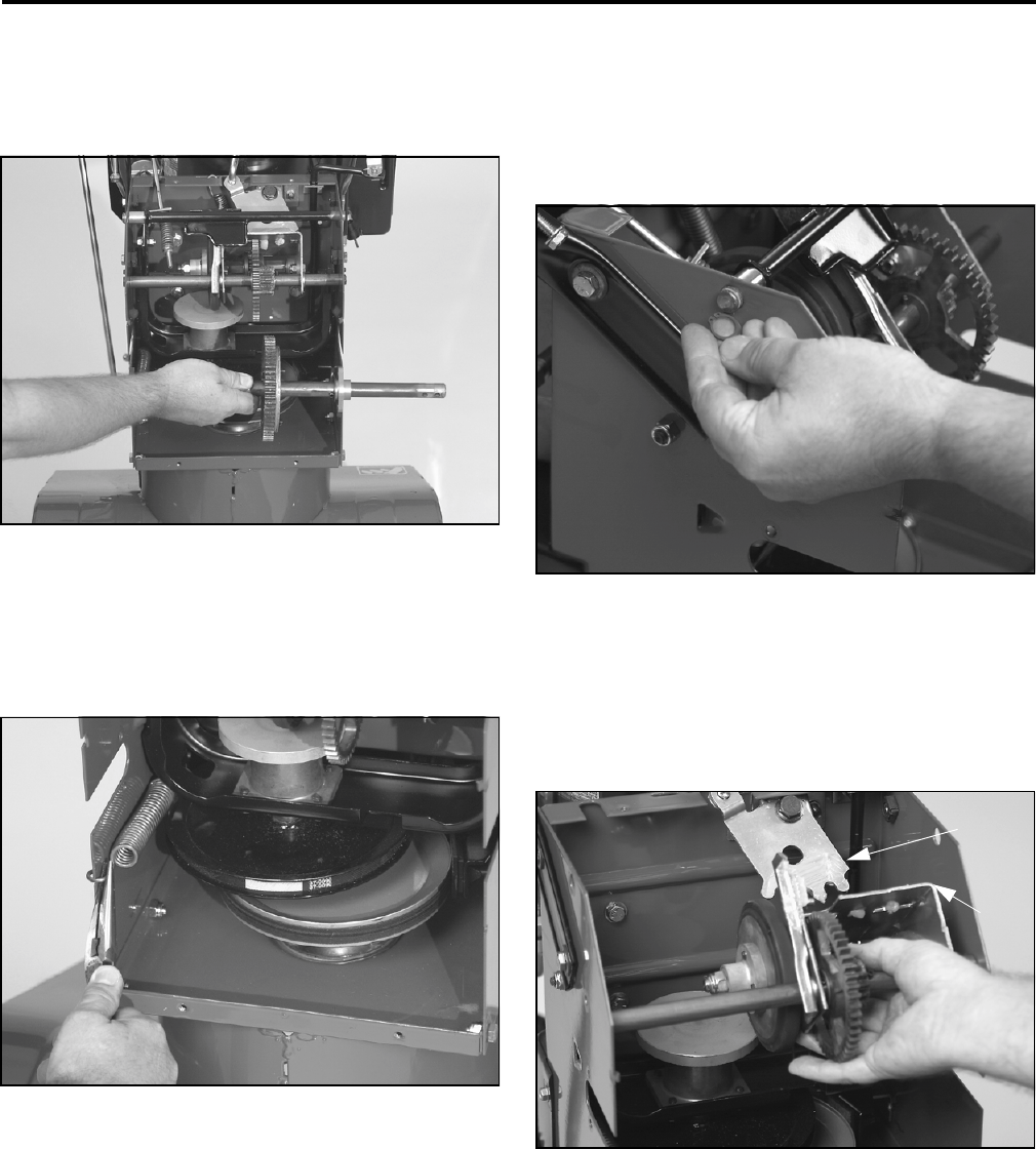
6. Remove 4 self-tapping screws that secure the
axle bearings to the traction frame. Lift the axle
and bearings out (Figure 89). Slide the bearings
and thrust washers off the axle.
Figure 89
2773-074
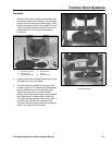
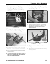
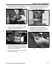
7. Disconnect the shift rod and traction drive rod.
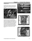
8. If the friction plate frame spring (traction belt
tension) did not unhook when the belt was
removed, unhook it now (Figure 90).
Figure 90
2773-077
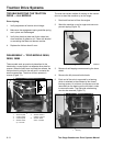
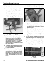
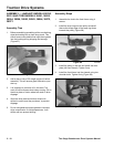
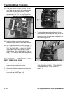
9. To remove the traction engagement assembly,
remove the retaining ring on the left side of the
frame. Note: Some older models use a cap screw
through the side plate into the end of the shaft.
Slide the shaft to the side and it will disengage
from the chassis (Figure 91).
Figure 91
2773-079
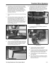
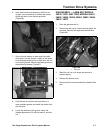
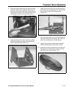
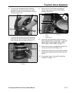
10. To remove the friction wheel and bracket
assembly, remove the bolt that goes through the
side plate into each end of the shaft. The gear
quadrant fingers should disengage themselves
from the sliding bracket that contains the friction
wheel (Figure 92).
Figure 92
2773-081
1
2
1
.
G
ear qua
d
ran
t2
.
Slidi
ng
b
rac
k
e
t


