


1. Route the valve control wires between the valves and
the controller.
Note: Using 18 AWG (0.75mm
2
) multi-wire sprinkler
valve connection cable is recommended. This cable
is insulated for direct burial and is color-coded to sim-
plify installation.
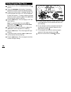
2. Attach the white color-coded wire from the cable to
one
wire from each valve solenoid. (Either solenoid
wire can be used for this connection.) This is called
the valve common wire.
3. Attach a separate cable wire to the remaining wire
from each valve solenoid. Make a note of the wire
color code used for each valve and the watering sta-
tion it controls. You will need to have this information
when connecting the valve wires to the controller.
4. Secure all wire splices using twist-on wire connectors.
To prevent corrosion and possible short circuiting,
use a grease cap or similar waterproofing method to
insulate each connection.
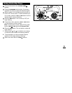
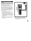
5. Route the wire cable into the controller through the
large opening in the base of the housing or through
PVC conduit if it is installed. Strip insulation back
1/2" (13mm) from all cable wires.
Note: The GreenKeeper 212 has snap-in wire termi-
nals. To attach wires, simply raise the lever, insert the
stripped wire, and press the lever down to secure.
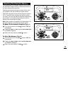
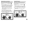
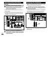
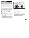
6. Referring to the Controller Components on page 5 and
the diagram above, secure the valve common wire to
the terminal labeled COM (12). Connect the individual
station valve wires to the appropriate station module
terminals (15). Connect the master valve wire (if
applicable) to the terminal labeled PUMP/MV (13).
Note: Connecting a master valve or pump start relay
is optional and may not be required in your sprinkler
system.
Connecting The Valves
23
BATTERY
Valve Common
Wire
Station
Valves
Master
Valve