


Assembly Section 2-11
ASSEMBLY
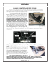
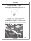
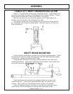
MANUAL SWITCH MOUNTING
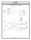
Refer to the parts section for wiring diagrams. Remove right side cowl panel,
tach panel, and hour meter panel for access to the wires.
Route the red wire from the switch box to the bare electrical plug in the fuse box,
or other un-used “keyed” hot wire. NOTE: +12 VOLTS ELECTRICAL POWER
MUST BE TAKEN FROM A SOURCE LOCATION WHERE IT IS LIVE ONLY
WHEN THE IGNITION SWITCH IS IN THE “ON” POSITION. THIS WIRE MUST
BE FUSED AT THE SOURCE LOCATION.
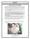
Drill a ½” hole in the 9” X 5” right side panel to route the green safety switch wires,
and white wire to be connected to the hydraulic solenoid valve.
The switch box is to be secured to the operators side of the control handles, or
valve stand.
The green wires will connect to the neutral safety switch blue wires, located on
the back of the ignition switch, under the cowl panel.
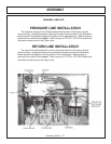
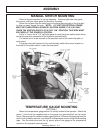
TEMPERATURE GAUGE MOUNTING
(OPTIONAL)
Mount the temperature gauge where it is clearly visible to the operator. Attach the
green (-) wire from the negative post on the gauge to a grounded bolt on the tractor
frame. Remove paint if needed to make a good ground. Remove the pipe plug from the
side of the hydraulic reservoir, and install the temperature sensor using thread sealing
tape. Run the white wire from the (s) sensor post of the gauge to the temperature
sensor on the hydraulic reservoir tank.