


Getting Started
CFG280 User Manual
7
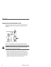
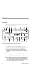
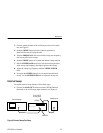
14. SOURCE Button. Selects between internal and external counter
input. When you push the button in, the counter readout displays
the signal frequency count from the EXT COUNTER INPUT.
When you push the button out the counter readout displays the
frequency count of the signal being generated by the CFG280
Function Generator.
15. MAIN Button. Selects between two voltage ranges: 0 V
p-p
to
2 V
p-p
or 0 V
p-p
to 20 V
p-p
. This control is used with the
AMPLITUDE control to set the voltage level of the MAIN OUT
signal.
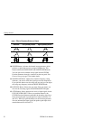
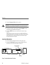
16. AMPLITUDE Knob. Adjusts the voltage within the presently
selected range. This control is used with the MAIN control to set
the voltage level of the MAIN OUT signal.
17. DC OFFSET Knob. Sets the DC level (and therefore the polarity)
of the MAIN OUT signal. This knob has no effect until you pull
it out.
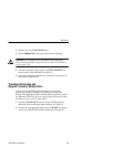
18. SWEEP WIDTH Knob. Adjusts the range of frequencies that are
traversed by each sweep.
19. SWEEP OUT BNC. This connector sends sweep signals that you
can adjust with the sweep controls. You can use a sweep signal to
synchronize an external device such as an oscilloscope.
20. MAIN OUT BNC. This connector sends sine, triangle, square,
and positive and negative pulse/ramp signals.
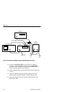
21. SYNC OUT BNC. This connector sends TTL trigger signals.
Amplitude and DC offset adjustments do not affect TTL trigger
output.
22. EXT COUNTER INPUT BNC. This connector can accept
external signals with frequencies between 1 Hz and 100 MHz.
23. FREQ FINE ADJ knob. Allows small adjustments in output
frequency.
24. FREQUENCY Dial. Determines the frequency of the function
generator output, within the range set by the MULTIPLIER
buttons.
25. POWER switch. Toggles instrument power on and off.