Getting Started
CFG280 User Manual
5
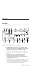
The 1 and 0.1 LEDs provide accurate indication for the two
lowest frequency ranges. For example, if the FREQUENCY dial
is set on 2.6 and the 1 LED is lighted, the function generator
output frequency is 2.6 Hz.
5. FREQUENCY Range LEDs. Indicate the range (either MHz or
kHz) of the reading shown on the counter readout. These LEDs
also indicate the frequency range of the function generator
output. For example, if the FREQUENCY dial is set on 9, the
10-1M LED is lighted, the kHz LED is lighted, and the counter
readout shows .090, then the function generator output frequency
is 0.090 kHz = 90 Hz.
NOTE. You must have the SOURCE button set on INT (pushed out) to
differentiate between the 10, 10
2
, 10
3
(kHz),10
4
,10
5
, and 10
6
(MHz)
generator output ranges.
6. SEC LED. Lights when the frequency counter is in PERIOD
mode. The counter readout does not show frequency in hertz, but
period in seconds. For example, if the FREQUENCY dial is set at
4, the 1 multiplier LED is lighted, and the SEC LED is lighted,
the counter readout displays a value close to 0.250. This indicates
the generator output period is .25 s (the frequency is 4 Hz).
7. MULTIPLIER Buttons. Set the frequency range. The left button
raises the range by a power of ten and the right button lowers the
range by a power of ten. For example, if the FREQUENCY dial
is set to 4.7 and the output is set to kHz, when you press the left
multiplier button the output frequency will jump from
4.7 10
3
Hz (4.7 kHz) to 4.7 10
4
Hz (47 kHz).
8. FUNCTION Buttons. Select the type of waveform generated:
sine, triangle, or square.
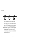
9. Symmetry Buttons. Select either positive pulse/ramp or negative
pulse/ramp (see Table 1 on page 6). When you push either
button in, the output frequency is 1/10 of the value shown on the
FREQUENCY dial. When you push both buttons in, the output
frequency is 1/19 of the value shown on the FREQUENCY dial.


