PN 8500-0150, Rev. A, May 2005 7
Operating Manual
Operation
3 — Operation
Neither the 5401 nor the 5402 have any external manual controls. Signal output amplitude is
controlled by internal potentiometers, which are located as described in Chapter 2. All
operational control of the DRO is accomplished by means of an RS-232 input/output port.
RS-232 Input/Output
The DRO has been equipped with an RS-232 interface using a 13-pin MS type connector
designated as J14 RS232 on the 5401, and using a DB15 connector designated as J3 on the
5402. This serial port can be used to communicate with the DRO from a computer or a 'smart
terminal.' All communication is in the ASCII format. The standard character protocol is 9600
BAUD, one start bit, eight data bits, none for parity, and one stop bit.
The connector pin assignments and designations for both connectors are given in Chapter 4.
All communication to the DRO comprises two or three categories of characters. The first
category is a single character which is always an ASCII $ (Hex 24). This is the
attention/log-on character. The second category is an ID ASCII character which is a
command to the unit. The third category (which may or may not be applicable) is a series of
ASCII data bits to input data into the DRO. Leading zeros must be used where necessary. For
example, if the number to be input is fifty-two, and if the data field is a four digit number, then
it must be entered as 0052.
All command message inputs and response outputs end with Carriage Return (CR), Line
Feed (LF).
When burst status is on, the unit will not send a response. However, configuration parameters
can still be changed.
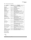
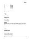
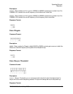
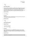
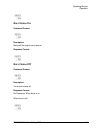
Table 1 on page 8 shows the functions available. The ASCII character is shown followed by
its HEX equivalent. Comments pertaining to that specific function are also included for clarity.
If a mistake is made while inputting new characters (prior to the last character), issuing
the "$" character will cause a reset, and the new (correct) characters can be input.


