Operating Manual
Installation
PN 8500-0150, Rev. A, May 2005 6
Symmetricom 5402 Installation Procedure
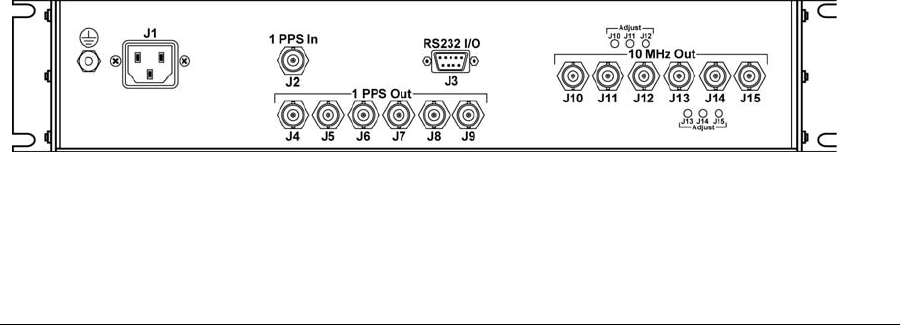
1. Install the unit in the desired location and connect the unit to an AC power source. Refer
to Chapter 4 for specifications and connector designations and locations.
2. Connect the 1 PPS input to its 1 PPS source and connect the 1 PPS and 10 MHz outputs
to their desired destinations.
Connection to the RS232 I/O is not necessary for operation, but it is desirable in order to
monitor status or enter new control parameters.
Symmetricom 5402 Initial Operation
Upon completion of the installation:
1. Apply power to the unit by turning on the front panel ON/OFF power switch. Observe that
the green POWER LED indicator illuminates.
2. After approximately five minutes, the internal Rubidium oscillator will have attained lock
(resonance). The 10 MHz outputs are now stable for use. Disciplining of the Rubidium
oscillator will begin once 1 PPS input is present.
The 5402 is now operational and will begin to discipline the Rubidium using the control
parameters that were previously stored in battery-backed RAM when the unit was last
powered-down.
Symmetricom 5402 Adjustments
The amplitude of each of the 10 MHz outputs can be individually adjusted with
potentiometers located on the 3 Channel Distribution Amplifier (Assembly 35039). Access to
these potentiometers is through holes in the rear panel. Each hole (and its associated
potentiometer) is clearly labeled as to which output it adjusts. See Figure 4 for the location of
the adjustments.
Figure 4 Symmetricom 5402 Rear Panel


